I would recommend to invest in a 4S active balancer with leds like Broodio (see link from April and me above). Then you will know if your cell voltage is equal or not. Measuring only the total voltage is not safe as 3.3 + 3.1 +3.5 +3.7 is also 13.6V but not a good situation. When your cells get older this situation may exist one day..All this...is why I bottom balanced my cells and keep max charging voltage to 3.4v/cell or 13.6v for my 12v nominal pack.


You are using an out of date browser. It may not display this or other websites correctly.
You should upgrade or use an alternative browser.
You should upgrade or use an alternative browser.
Why cheap BMS controllers can't do high currents
- Thread starter robaroni
- Start date
Keith C
Ahhh, the sharks have him.
Thanks all for the links. I scratch my head at Russian Ali by a Chinese company! LOL
Then scratch it again because it shows an active balancer with 12 little switchers on it and calls it specifically a "13s". Huh?
gehowi; I'm perplexed by how those BMSes all have about 80A worth of wire while stating 200A! Yeah rrrrrright.
Then scratch it again because it shows an active balancer with 12 little switchers on it and calls it specifically a "13s". Huh?
gehowi; I'm perplexed by how those BMSes all have about 80A worth of wire while stating 200A! Yeah rrrrrright.
Chinese specs have to be divided by 3. Certainly for their mosfets and there are a lot of them inside their BMS..I'm perplexed by how those BMSes all have about 80A worth of wire while stating 200A!
sajjen
New Member
The switchers on those boards are connected between two adjacent cells. On the 13S board there are twelve devices, one for each adjacent pair. The balancing only takes place between the two cells, not on the whole pack per se.
I disconnect my BMS and my active balancer whenever I work on my packs . Definitely !. If you dont you will short them out at some point. Just a mass of wires in there and loose connectors hanging about if you take a cell out or make a change.If its not connected it cant blow . Ive blown 2 active cell balancers so far by a connector hitting another terminal on the way off and by the exposed solder connection where the wiring loom enters the board touching other terminals.
Any other terminal is going to put better than 6 volts through that channel sense wire and blow the channel. Components light up but the board doesnt burn.
Any other terminal is going to put better than 6 volts through that channel sense wire and blow the channel. Components light up but the board doesnt burn.
Keith C
Ahhh, the sharks have him.
gehowi.. I see... LOL
April; We need a little terminal board with fuses to use in BMS octopuses.
sajjen; !!! I didn't realize those active balancers only balance to the immediate neighbors. Weird. I'm trying to get my head around that..
So let's say you have a high battery and it's next neighbor is at the high limit already...
It goes ahead charging that one to above the limit? Then that one's balancer shoves it to it's neighbor? What happens if the last one in the stack is fully charged and has nowhere to send it's over-charge?
Or does the neighbor reaching max stop balancing?
I thought active balancers sent excess to a low cell.
I am waiting for a second post by a guy analysing these but he recons the low cell is fed by the highest and it feeds through adjacent cells to get to the lowest . I dont understand this either just yet but it will all become clear . I am convinced they work well though and are a worthwhile addition to your battery protection.April; We need a little terminal board with fuses to use in BMS octopuses.
sajjen; !!! I didn't realize those active balancers only balance to the immediate neighbors. Weird. I'm trying to get my head around that..So let's say you have a high battery and it's next neighbor is at the high limit already...
It goes ahead charging that one to above the limit? Then that one's balancer shoves it to it's neighbor? What happens if the last one in the stack is fully charged and has nowhere to send it's over-charge?
Or does the neighbor reaching max stop balancing?
I thought active balancers sent excess to a low cell.
I will run my terminal wires to just such a board Keith but no fuses necessary as its minimal current (well I guess when it fried a channel component a fuse would have been appropriate but it would be small) ,just a voltage sense that does not like 6 volts. With just one loom going off to the side of the battery any other devices including BMS, active balancer and cell reader can be attached straight to that so no thousand wires all over the top.
Last edited:
May be some balancers work like this but the Broodio 16S seems to distribute power allover the cells.I didn't realize those active balancers only balance to the immediate neighbors.
Because the leds for several cells (not next to each other) are lit sometimes and after some time they go out one by one. The cellvoltage is more equal when it stops. If it would use only the neighbors, it would not be possible.
A balancer with coils is the best solution (if well designed). Capacitors are losing energy after charging from the high cells, so they can only partially transfer energy to a lower cell.
The coil systems use a coil to store a small amount of energy and boost the voltage up to a higher level than the low cells. This happens thousands/sec with less losses and small heat on the PCB. It's a very complicated process but most efficient.
CerealKiller
New Member
- Joined
- Jan 28, 2020
- Messages
- 25
May be some balancers work like this but the Broodio 16S seems to distribute power allover the cells.
Because the leds for several cells (not next to each other) are lit sometimes and after some time they go out one by one. The cellvoltage is more equal when it stops. If it would use only the neighbors, it would not be possible.
A balancer with coils is the best solution (if well designed). Capacitors are losing energy after charging from the high cells, so they can only partially transfer energy to a lower cell.
The coil systems use a coil to store a small amount of energy and boost the voltage up to a higher level than the low cells. This happens thousands/sec with less losses and small heat on the PCB. It's a very complicated process but most efficient.
Please can you point in the direction to get this type of active cell balancer with a coil system?
robaroni
New Member
- Joined
- Sep 30, 2019
- Messages
- 35
Thanks for all the comments everyone!
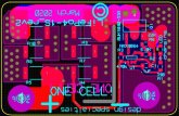
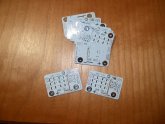
Here's the circuit I designed to keep my batteries in balance on my 576 cell 48V pack 16S-36P. it works very well with my two charge controllers on my system which go up to ~60amps if I remember.
I keep the max charge voltage to 54.4 or ~3.4V / cell.
Because my batteries are removable there may be some small resistance between lines, although I did test it at over 100 amps draw with very little drop. What I did find was that, even at 3.4V / cell, some legs did go over 3.6 volts so I designed this balancer :
Attachments

robaroni
New Member
- Joined
- Sep 30, 2019
- Messages
- 35
I tried that balancer and found it didn't keep my pack in balance. I forgot what I tested the current at but it was not as advertised.
7.39US $ 25% OFF|Bms 3s 4s 6s 7s 10s 12s 13s 16s 17s 1.2a Balance Li-ion Lifepo4 Lithium Battery Active Equalizer Balancer Energy Transfer Board - Battery Accessories & Charger Accessories - AliExpress
Smarter Shopping, Better Living! Aliexpress.comwww.aliexpress.com
robaroni
New Member
- Joined
- Sep 30, 2019
- Messages
- 35
May be some balancers work like this but the Broodio 16S seems to distribute power allover the cells.
Because the leds for several cells (not next to each other) are lit sometimes and after some time they go out one by one. The cellvoltage is more equal when it stops. If it would use only the neighbors, it would not be possible.
A balancer with coils is the best solution (if well designed). Capacitors are losing energy after charging from the high cells, so they can only partially transfer energy to a lower cell.
The coil systems use a coil to store a small amount of energy and boost the voltage up to a higher level than the low cells. This happens thousands/sec with less losses and small heat on the PCB. It's a very complicated process but most efficient.
I tried this balancer, actually it's the one I tested that shows exactly what I'm talking about. Yes, if you're going to do small cells with minimum charge current they will work but don't expect more. It still has to follow the wires back to the controller to dump current to other batteries. It just won't do an amp well with thin wires like the one I got had.
The best solution is balancers across each cell. I might design a distributed controller like this one but it will be a lot more robust.
Keith C
Ahhh, the sharks have him.
So your balancer is the more typical resistor-dump style. Nice. How's it working for you? Are you finding an amp to be enough? I'm doing one that's an amp but I'm hoping an amp is actually useful for 220AHr packs. I can argue it isn't or is. It's hard to quantify.
robaroni
New Member
- Joined
- Sep 30, 2019
- Messages
- 35
So your balancer is the more typical resistor-dump style. Nice. How's it working for you? Are you finding an amp to be enough? I'm doing one that's an amp but I'm hoping an amp is actually useful for 220AHr packs. I can argue it isn't or is. It's hard to quantify.
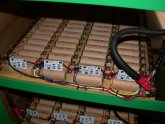
My bank is 36P @ 5.5A ~200A total. What I do is keep the single leg at 3.4 volts. I use very little if any capacity and I find keeping the battery under the high slope of the charge curve keeps any batteries from charge runaway at lower internal resistances. The balancers work very well, each has an LED that comes on when it's loading the 36P leg.
I checked the design using SPICE simulation and built it with .1% resistors. I isolated any heat from the comparator by using routing lines on the boards.
The way I set the boards up you can change resistances to increase the current. In my case I set up six 2.2 ohm 2W resistors to give a total resistance of 3.6 ohms.
I found setting the cut in voltage of the comparator to around 3.5V and with hysteresis off at around 3.2V the Leg never runs away.
So the math is 3.5V / 3.6 = ~.972 amps clamping current. Power of each resistor is .972^2 x 3.6 = 3.4W / 6 = .566W per resistor so you see I have a lot of headroom if I want to increase the current clamp. The drive mosfet is ~55A so this thing idles along pretty well. You can see random individual come legs come on and go off.
Keep in mind that I have excellent charge controllers feeding the bats. They switch off if the voltage drops below a specific point so I don't have to worry about low voltage battery damage. Also it looks like the bats are starting to stabilize in the system.
If you want to try one of my boards PM me and I run out a rev2. I have rev3 boards coming in but all they do is add a fuse to the board which you can add externally on the rev2 boards.
Keith C
Ahhh, the sharks have him.
I found setting the cut in voltage of the comparator to around 3.5V and with hysteresis off at around 3.2V the Leg never runs away.
!!!!?! I would've expected something like cut-in at 3.50V and cut-out at 3.45V. Doesn't 3.2V leave that cell (cell='leg'?) substantially below the other cells at the end of a charge cycle?
If you want to try one of my boards PM me and I run out a rev2. I have rev3 boards coming in but all they do is add a fuse to the board which you can add externally on the rev2 boards.
Super appreciate the offer! Very kind of you. I will decline though since I'm actually building a BMS with a chip that includes the balancing function.
What I haven't managed to suss-out yet is how this all works when you have charger trying to charge a battery and one cell is low capacity and trying to over-charge. The balancer kicks in and tries to drain the cell while the charger is still trying to charge it. The charger could be belting out 30A while a puny balancer is only shunting 1 measly amp. I'd imaging that one cell is going to force the battery out of charging. I'll have 8 batteries in parallel each with it's own BMS. If one cell in one battery is about to overcharge that battery has to drop out of the herd. Since the rest of the herd is still charging the drop-out is going to fall behind and won't be able to rejoin the herd until.... still grappling with this.
robaroni
New Member
- Joined
- Sep 30, 2019
- Messages
- 35
Yes, right typo 3.42 V!
For my bank I set my charge controller to ~54.4V (48V system 3.40 V per leg). This way the clamps aren't fighting the charge controller. This is important, you don't want the charger high total pack voltage to be above the low cut off voltage of each clamp comparator. A charge voltage that pushes each leg above the clamp would cause problems. The clamp is designed to keep any leg that drifts above 3.5V in check so what you invariably have is some legs with, say, 3.30 volts and others with 3.50 V.
So I have 16 clamps, that's 16 amps of clamping power although it will never happen that all the clamps are on at the same time IF the total charge voltage is below the 3.42V per leg times 16.
I notice on my bank if a leg starts to rise above the rest the clamp kicks in for a few minutes then drops off. Once the pack stabilizers you may see a clamp come on now and then but it really doesn't diminish the total pack power. It's just a safety check.
My advice is not to get to complex with the balance design. I made a solid design, checked it in SPICE simulation and then checked it for several hours under load. I think load transfer designs can run into trouble. Once you get away from a balancer that sits across a leg you start to introduce other factors like wire size, wire length and voltage accuracy and drop. I specifically got away from shutting off uC's to check battery voltage because you run into settling time variance problems. You want to avoid that as far as I see it.
Keith C
Ahhh, the sharks have him.
I notice on my bank if a leg starts to rise above the rest the clamp kicks in for a few minutes then drops off. Once the pack stabilizers you may see a clamp come on now and then but it really doesn't diminish the total pack power. It's just a safety check.
Leg.. You gotta stop calling cells 'legs'. In the electrical realm 'leg' has many meanings and "cell" is never one of them.
Okay! I think I see what you mean. Balance above the expected per cell charge voltage. That makes a lot of sense and I had not heard that before.
During the kick in and out of your balancers, is this after AND during charging?
I think load transfer designs can run into trouble. Once you get away from a balancer that sits across a leg you start to introduce other factors like wire size, wire length and voltage accuracy and drop.
The complexity sure skyrockets with charge transfer schemes and many failures could lead to quickly drained below cutoff cells. I looked at transfer schemes and finally dumped them all for resistive dissipation methods.
robaroni
New Member
- Joined
- Sep 30, 2019
- Messages
- 35
Leg.. You gotta stop calling cells 'legs'. In the electrical realm 'leg' has many meanings and "cell" is never one of them.
Okay! I think I see what you mean. Balance above the expected per cell charge voltage. That makes a lot of sense and I had not heard that before.
During the kick in and out of your balancers, is this after AND during charging?
The complexity sure skyrockets with charge transfer schemes and many failures could lead to quickly drained below cutoff cells. I looked at transfer schemes and finally dumped them all for resistive dissipation methods.
Legs aren't cells, there are 16 legs in the nominal 48V bank, each leg has 36 cells in parallel.
Yes, during, once the charger is off or drops significantly, let's say at night when the modules aren't producing power or it gets overcast and the PV array doesn't put out much the pack comes into balance, actually very quickly. At that point my legs are usually within 25 or 50 mv of each other.
By the way the hysteresis is built into the comparator (MAX9064 in my case) Maxim does make a comparator that you can set your own hysteresis on but I didn't find it necessary. I did use .1% resistors. I like the MAX 9064 it has a built in ref which saves using a 431 voltage ref and its small. The whole board is SMD and well under 50mm square.
Similar threads
- Replies
- 1
- Views
- 222
- Replies
- 29
- Views
- 963
- Replies
- 22
- Views
- 684