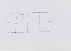
A confidentiality agreement with my employer means I cannot post the actual official circuit on the internet, but I can sketch something from memory if that would help.
They are all a very conventional buck converter stage that consists of a electrolytic across the dc input from the solar panels, a high side mosfet switch, a fast recovery catch diode, a series inductor, then a second electrolytic after the inductor across the dc output to the battery.
Five basic components.
That, when driven with a suitable duty cycle will decrease the dc solar panel voltage, and increase the dc charging current, as well as control the loading on the solar panels.
Its this duty cycle control that determines what the whole thing does. It can be given a whole range of functional features, including optionally power point tracking.