diy solar

diy solar

Will Prowse Vids: Solar Inverter Control w/ Optocoupler SSR and BMS (Intermediate level)

I'm not sure I agree with this one. While it works, you're bypassing the safety mechanisms of the BMS and need to ensure you place appropriate fuses in-line with the inverter/load to protect the current draw and a potential short circuit.

Factoring safety variables into a design is inherently implied in these videos, but it could be beneficial to provide an overview as the audience increases.


Proposing an alternative... a Victron Battery protect would be the better option and is equivalent price-wise. There are 65/100/220 amp options.

https://www.victronenergy.com/battery_protect/battery-protect
 
Last edited:
I'm not sure I agree with this one. While it works, you're bypassing the safety mechanisms of the BMS and need to ensure you place appropriate fuses in-line with the inverter/load to protect the current draw and a potential short circuit.

Factoring safety variables into a design is inherently implied in these videos, but it could be beneficial to provide an overview as the audience increases.


Proposing an alternative... a Victron Battery protect would be the better option and is equivalent price-wise. There are 65/100/220 amp options.

https://www.victronenergy.com/battery_protect/battery-protect
It is well documented by victron that battery protect is not to be used between batteries and inverter.
 
Correct, but you can use the remote on/off switch to trigger the inverter on a fused circuit - it's essentially the same thing and you can now manage your remaining DC loads through the same battery protect. You get an alarm circuit and a warranty, and the option to use a cheap BMS for charge regulation only.

My main point was more around the safety dynamic. Folks need to factor these in when working around a BMS.
 
Last edited:
I'm not sure I agree with this one. While it works, you're bypassing the safety mechanisms of the BMS and need to ensure you place appropriate fuses in-line with the inverter/load to protect the current draw and a potential short circuit.

Factoring safety variables into a design is inherently implied in these videos, but it could be beneficial to provide an overview as the audience increases.

There is a fuse between the battery and inverter. Is that what you are talking about??
 
Correct, but you can use the remote on/off switch to trigger the inverter on a fused circuit - it's essentially the same thing and you can now manage your remaining DC loads through the same battery protect. You get an alarm circuit and a warranty, and the option to use a cheap BMS for charge regulation only.

My main point was more around the safety dynamic. Folks need to factor these in when working around a BMS.
Gotcha but then why pay way more to do same thing.
 
Depending on your overall setup, a few bucks more could net you a more capable solution with a commercial-grade product.

However, neither method solves the challenge of pre-charging the caps to mitigate current inrush at the inverter. It protects the BMS mosfets but the inverter could still be damaged.
 
I like the idea of most use of $s. As a newbie in pre-purchase study mode for my first DIY 24v 280Ah or 560Ah set of LifePO4s ... I will likey spend the money to see all the details (for my initial learn curve that hopefully without headache cycle. What I wonder about with this option: How would this lower cost option do on the balancing the cells chore and compared to BMSs that are matched to higher amp draws / like 4 or more time more than that that 60 amp rated BMS (think that what it was) ... Yes, I could see how to trust a better MPPT to charge a LifePO4 without killing it, especially if you can fine tune charging details. and see how this relay cutting off the inverter draw setup protects battery cell from getting too low. Also learned form this clip (Thank yow Will) that low voltage and ongoing charge is likely biggest danger for killing a LifePO4 cell. (on top of charging during freezing temps).

Wondering about two questions: Which specific wire of BMS to connect to relay? 2) How does the cell balance abilities compare to the Daly BMS in the 200 Amp - 300 Amp ratings? I am sure I could study the specs more and get answers. Wonder if anyone know off the top of their brain?
 
Last edited:
correction to the video, he says he placed the opto relay in serie with the switch.. on the video , the wiring is not obvious and operating the switch back and forth is misleading.
the problem is none of the connection (serie or parallel) allows you to operate both state ON/OFF.
in paralllel you can force ON, but not OFF (if on e of the contact is ON, operating the other one will do nothing)
in serie, it is the contrary. You can force OFF, but you cannot force ON, if a switch is open , closing the other one will do nothing.

For safety, serie is better, so you always left the mechanical switch ON, so the operation is done by the opto. If there is problem, you can still
switch off with the mechanical switch.
In that case , the best would be to replace the original switch with an emergency kill switch.
images
 
Last edited:
I am not sure about your take on that. I got oca Relay part is likely NC (normally closed), and relay switching part (not the coil) and tkind of replaces the inverter switch (not MPPT battery charger) of that all in one unit. The BMS to Oca -Relay wires through coil /actual an oca -electronic mechanism ) look like it when to positive terminal of battery (going by memory) w ground going through BMS via wire connection to BMS that was not specifically shown... If that was how it was? ... it could turn off inverter draw of battery when one cell was too low to be safe for further draw down, and if charged back up to above danger zone, grounded oca relay would be released back to NC postion and turn the inverter back on all automatically. Take was my take without really knowing all the specifics or having a wiring diagram to view. I liked the idea of less expensive options, and learned more all the time.
 
Last edited:
all was clearly shown.
the bms act like a switch between P- et positive of battery , the optical switch trigger input being in the path.
the other side of the optical switch is put in serial with the inverter switch (Will desoldered the black wire from the memechanical switch and soldered the optical output between the free red wire and the free pin of the mechanical switch.
that is a serial mount, where you just cut a wire to insert something.
 
Last edited:
1585392713728.png
1585393212719.png

and yes it is unfortunate to extend a black wire with a red one and isolating with a green/yellow shrink tube.
but that is DYI after all, isn'it ?
 

Attachments

  • 1585392711936.png
    1585392711936.png
    470.8 KB · Views: 10
  • 1585393211378.png
    1585393211378.png
    403.2 KB · Views: 10
OK, Great to see a lower cost strategy /way to protect LifeP04s with less $ . Those added views make it much clearer to me. So now I think: that Oca-Relay is a NO (normal open curciut) that closes to to keep the inverter running via small current running + of Battery, through Oca-Relay to P - of BMS (P- must be negative on BMS, & P stand for post) ;... so NO Oca is held closed (Oca - electronic super low current draw) to keep inverter running until BMS cuts off round for holding Oca -relay closed, & open curcuit cut out inverter that most importantly stops further battery draw down; all while the MPPT , directly wired to battery, can continue to charge batteries. I can see how it all on automatic. When low cell get higher, the BMS with ground curcuit through Oca Relay and inverter is back on.

What I am left wondering about for a larger Ah LifePO4 set up, like maybe a 280 Ah I am considering... I wonder how the Daly 60 amp rated BMS would do on the balancing the cells chore, as compared to a Daly w specs for larger amps, like 150 -200 amps. I would expect the Daly BMS rated for larger amp capacity would have better cell balancing abilities than the smaller one only rated for 60 amps, ... but I do not know that. an not heading to a spec study at present, to see if any specs info. might answer my wondering. Somebody reading this might know off top of their head.
 
probably not. If you use only the balancing part of the BMS, it is just about measuring voltage (more specifically each cell is measured).
So no current is involved here and the discharge curve is pretty the same at any current , the battery being 10Ah or 100Ah.
the only current the BMS will deliver is the one supplied to the optical relay.
What you have to check is if the BMS is not too much finicky about discrepencies between cells.
a small BMS for small batteries could be set to finer settings that a BMS for a big battery.
the consequence would the relay trigerring on the OFF state too easily.
By the way this is a clever trick to give for cheap a feature to a device that was delivered without.
ideally i would mount the optical switch inside the MPPT box, add a led to show status, and a connector
to allow easy connect/disconnect of the BMS.
 
Last edited:
What is the power consumption of an octocoupler like the Opto 22 DC60S5 will used in his video? wondering how this contributes to the total power consumption of the BMS for lower power systems. i.e. if the Daly is pulling 30uA... but this octo is pulling 100mA, then that might be significant loss in low power installations.
 
The datasheet says the input side is 1 kOhms but in reality it's a bit better as it's 1 k in series with a LED and you can expect a 1 to 2 V drop across the LED. So if you use 12 V the current will be around 10 mA.

NB: the leakage current on the power side can go as high as 1 mA, it might be a problem with really sensitive inverters (will not turn off even if the relay is off). Should not be a problem for 99 % of inverters though.
 
thanks @BiduleOhm . i was doing that math too... 12v/1000ohm = 12mA. was wasn't entirely sure how to interpret that 1000 ohm impedance in the spec.
 
thanks @BiduleOhm . i was doing that math too... 12v/1000ohm = 12mA. was wasn't entirely sure how to interpret that 1000 ohm impedance in the spec.
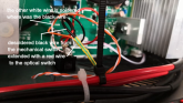
I have that SSR now wired up and working with chargery BMS. measured 13k ohm when relay is closed with my fluke. Infinite when open.
Does the fluke use 9V signal to measure?

I bench tested before installing. I was surprised that unlike a normal solenoid relay I couldn’t pass through it a ground signal. The output side was grounded even if the relay was open. So I had to pass a 12V signal through it. Then it worked as expected.
 
You can't measure the resistance if you power the relay at the same time. But you can measure the current if you want.

You can... my guess is you wired it backwards so yeah, then it's equivalent to a diode as pretty much any mosfet will have a parasitic body diode included.
 
I do like the idea of using the Victron Battery Protect to provide redundancy to the low voltage load shutdown.
The power for the inverter SSR and the DC load panel in my RV could be ran thru it. I like the idea of remotely controlling it with the Chargery BMS and if for some reason that fails, it will do the shutdown itself. Don't want to come back to my RV and find the battery completely dead. ... just gotta look at how that remote control works on the Battery Protect.
 
You can't measure the resistance if you power the relay at the same time. But you can measure the current if you want.

You can... my guess is you wired it backwards so yeah, then it's equivalent to a diode as pretty much any mosfet will have a parasitic body diode included.
I'm an ME not EE and beyond Ohms law, a lot of the limited coursework is faded in my brain :cool:
I do still learn though! And enjoy it!

Thanks for the info on your first statement. Note, I didn't power the load side of the relay to measure, just the control side. Though this SSR isn't labeled as such, it'd be like measuring across terminals 30 and 87 on the type of relays which I'm familiar. Is it not possible to measure resistance of an SSR in this fashion?

As for wiring backwards, the trigger / control (side 85 / 86 is what I'm used to) is labeled + / -. I wired it per those labels.
Also, the load side vs. trigger sides have different terminal pads. The load side are substantially larger, including the bolt clamp diameter.

This isn't the actual relay (this might not be DC / DC but it looks like this. You can see the labels and the smaller connections on the trigger side.

What am I missing? image.jpeg

Thank you very much,

Doug
 
Oh you were talking about the load side. I thought you were talking about the control side.

It depends on the type of SSR but as a general rule I wouldn't consider using a DMM a reliable way to measure the load side resistance.

When I said backwards I was talking about the direction of the current, not a load/control side inversion. Most (all?) DC SSRs I've seen are directional, and as they usually use mosfets they act like a diode when in the open state, so you can pass current (with a 1-1.5 V voltage drop) in the reverse direction even when the control side is OFF.
 
Hmmmmm. so I could have wired the ground(s) on the load side backwards and it'd have worked? I didn't try that.
Thank you
 
Ok so my question is since their is much more to a complete system, the BMS that he has on top of the battery is this only Bing used to protect the circuit between the batt and the inverter? and if it is, then do you need a separate bms to protect all the rest of the circuits
 

diy solar

diy solar
Back
Top