Computerizer
New Member
- Joined
- Apr 23, 2022
- Messages
- 8
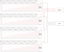
I'm putting together a 13S4P lithium pack, as shown:

I'm experienced enough and comfortable enough to figure out the wire sizing for all the solid-colored wires in my diagram, which are meant to carry the load. However, the BMS needs to be able to measure the voltage of parallel groups of cells and to discharge them for balancing. The dashed wires on my diagram are for that.
The BMS will only draw 42 mA when discharging, so for that purpose the wires can be quite small. However, I'm concerned that current could flow between the parallel strings via these wires. For example, at initial setup the third cell of the first string may have a lower voltage than the third cell of the second string, which seems like it would result in current flowing from the third cell of the second string into the third cell of the first string via these dashed wires.
Obviously I would try to ensure all the cells are relatively balanced BEFORE connecting them, but it's not going to be perfect. And perhaps there are other circumstances where an imbalance between parallel cells would occur that I'm not thinking of.
So ultimately the question is, do these wires need to be sized according to just what the BMS might draw, or do they need to be sized the same as the solid-colored main wires, or something in between? And why? (And, if something in between, how do I figure that?)
Thanks!