diy solar

diy solar

Wire Sizing

PaulLad

New Member
Joined
Jul 14, 2020
Messages
170
I found this chart in another post but I'm a bit confused by the "critical vs non-critical" columns. I assume a laptop would both fall under the critical column. My panels are 150' from my 12V solar generator and with 400 watts of panels I'll be generating 33 amps so according to this chart I'll need 3/0 aluminum wire? Does this sound right?DC_wire_selection_chartlg.jpg
 
I don't see that the chart is for Aluminum wire.

Non critical means the voltage drop has no impact except for lost efficiency. A 10% voltage drop might cause some sensitive equipment to malfunction.

A laptop has its own battery, so a failure in the charging system is likely not critical.

A 10% loss in your array voltage would only mean a 10% loss in array power, which has no other effect.

The panels should operate at higher voltage/lower current than the 400W/12V = 33.3A

What is the max input Voc of your charger?
What are your panels' Voc?
What are your panels' Imp?
 
Any chance you learned something from this?

 
This chart is for copper only and generally all DC wiring in batteries and inverters should be considered critical.

Solar wiring doesn't need to use this at all and only needs to be sized for amps no matter the length, but there is an economic loss consideration.

33A solar should use maybe 8 or 6 copper or 4 aluminum.
 
Solar wiring doesn't need to use this at all and only needs to be sized for amps no matter the length, but there is an economic loss consideration.

Can you elaborate on the economic loss consideration please? Do you mean by damaging equipment because of a high voltage loss?
 
Any chance you learned something from this?


I thought I did until I found that chart in another post and then wondered if my wires were way too small.
 
Ok I think I understand. You don't use 12, 24 or 48V. You use the actual VOC and IMP.

Yes that's it Paul, 12, 24, 48v are great for discussing batteries and nominal system size

But it makes sizing a solar array properly close to impossible, with the correct details (vmp/Voc) we can ensure the equipment will work together properly
 
Can you elaborate on the economic loss consideration please? Do you mean by damaging equipment because of a high voltage loss?

Voltage drop

So as an example , if you start at 12.5v and you had a 20% voltage drop on a cable , that would end up at only 10v (not high enough for most 12v equipment)

The 20% is lost to heat, the cable will warm up
 
Can you elaborate on the economic loss consideration please?
Yes.

Say that you have 400w at 33 amps and 12v. The NEC would require that your wire be sized for 1.25x33=41.25 amps, which would require 8 awg wire.

So 8 awg would be your safety minimum. Then the economic loss consideration would be:

8 awg - 12v - 150ft - 55% voltage drop = 210 watts lost on the wire

6 awg - 12v - 150ft - 35% voltage drop = 140 watts lost on the wire

So 6 awg is an optional upgrade, but it is probably economically worth the extra cost.

Btw, I think this is all predicated on bad numbers now that see them, your panels won't run at 12v and probably won't push 33A, we would need to see exact panel specs but that's not how any array works in practice
 
Last edited:
Btw, I think this is all predicated on bad numbers now that see them, your panels won't run at 12v and probably won't push 33A, we would need to see exact panel specs but that's not how any array works in practice
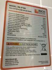
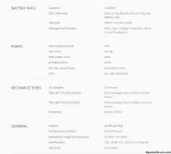
Here ya go. Thanks for the help.
 

Attachments

  • rich solar panel specs.JPG
    rich solar panel specs.JPG
    860.4 KB · Views: 6
  • EB240 specs.JPG
    EB240 specs.JPG
    164.8 KB · Views: 6
You're welcome. It looks like the EB240 can accept up to 60v input so if you have 4 of those panels I would wire them in 2 series, 2 parallel.

That would give you 45.2VOC with enough safety headroom, and 11.72 amps. 11.72*1.25= 14.65 amps for wire sizing, so 14 awg or larger.

14 AWG might lose 25% of the power at 150ft, and 12 awg lose 15%. Roughly.
 
4X100W in 2S2P config:

37Vmp
10.8A Imp

10 awg yields 8.75% voltage drop:


I would be fine with that. it simply means you'll lose 8.75% of your array power to heating the wire.
 
You're welcome. It looks like the EB240 can accept up to 60v input so if you have 4 of those panels I would wire them in 2 series, 2 parallel.

That would give you 45.2VOC with enough safety headroom, and 11.72 amps. 11.72*1.25= 14.65 amps for wire sizing, so 14 awg or larger.

14 AWG might lose 25% of the power at 150ft, and 12 awg lose 15%. Roughly.
Greatly appreciated. Sounds like 10 ga would be ideal. Can you share the formula for power loss per distance?
 
This chart also confuses me.

1) Circuit length generally means up and back, so distance is half of what they are stating?
2) Most homes are wired with 14 AWG for 15 amp circuit, 12 AWG for 20 amp circuits, and 10 AWG for 30 amps circuits, but the chart shows those gauges only valid for 20 feet at a 10% loss. Few homes, especially multi-story ones, have circuits that short (maybe 10 feet if 1) holds).
2A) Of course homes are wired with breakers rated at the same amperage of the above (e.g. 20 amp breaker fed by 12 AWG wire), and those breakers are rated at 80% continuous load, but that 20% delta evaporates pretty quickly on that chart as one bumps the distance.
2B) I've had some advice that NEC requires the wires to be 25% greater gauge to expected amperage. So if expected is 16amp, plan for 20amps. Feels like that is double counting if you equate "expected" to "peak", but lines up completely with "expected" = "continuous".
3) Worst reading I can think of: Want to carry 30 amps peek/24 amps continuous for 100 feet (200 foot "circuit") would require #2 copper wire?!?!

Clarification, along with concern every house I've even seen the wiring in is seriously off (and I've owned a number of rental homes so have seen a lot) please. Ex: a 50x30 home with an electrical panel in the garage (far corner) mostly wired up with 14 AWG shy a single 10AWG for a dryer.

Brain is frying when I think of 100 ft extension cords with the same gauges as my home wiring example.
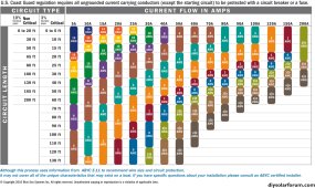

The chart is for marine applications and almost certainly for DC only - maybe even 12V. I NEVER rely on someone's chart and calculate voltage drop:


30A, 120V, 10awg is 3% drop @ 60 ft (one way).
 

diy solar

diy solar
Back
Top