diy solar

diy solar

YamBMS JK-BMS-CAN with new Cut-Off Charging Logic (open-source)

i assume you have different cable lenth or diameter from inverter to your battery or your batteries have very different internal resistance.
The inverter charges both batteries but one takes much more A than the other.
after you stop charging, that one gets discharged and charges the other battery.

This is not good and will cause big problems where one runs into OVP and the other does not. I bet you will destroy one or both BMS over time.

But without any detailed scematic how you physically connected your batteries like pages before mentioned, we cannot help you

Many of your problems could be related to that issue - you need to sort that out and fix that!

As it stands right now - i have no more issues while using the User-Defined settings - my battery cable length and gauge are approximately the same.... as i said earlier, i have fixed the wiring...spent all last night fixing it...if there was issues with the wiring i would know.

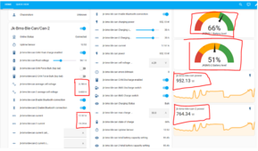
The average voltage from each other looks pretty close for a system that dont talk to each other so i am comfortable that there is no danger
the system behaves normal and near perfect
1710350224730.png

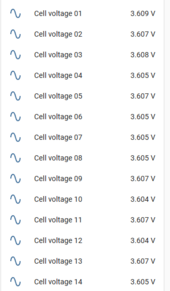
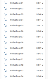
I also keep a close eye on the individual cells across both batteries and they are pretty much the same - so again no problems

the issue which was the last of my issues was to do with the Pylon protection settings which is not available (for edit) to the ordinary personnel - only if one has an API to edit the values I suppose

That is my conclusion based on the comparison of the values between the User-Define and the Pylon available editable parameters.
 
Jk-Bms-Ble-Can

1710351415268.png


Jk-Bms-Ble-Can-2
1710351497594.png


Jk-Bms-Ble-Can always lags by 0.033v and i understand why - and i know its normal and poses no danger to the cells. at rest... they do balance out.
 
Jk-Bms-Ble-Can

View attachment 201917


Jk-Bms-Ble-Can-2
View attachment 201918


Jk-Bms-Ble-Can always lags by 0.033v and i understand why - and i know its normal and poses no danger to the cells. at rest... they do balance out.
That seems like the "offset" / voltage measurement error problem I had.

If it was 0.033V for the entire pack I would understand.
But 0.46V difference across your 14s is more likely a lack of calibration of your jk bms in the jk bms app.

As I said I used to have 0.7V voltage difference for the full pack. First I thought it was a diode. Then it was probably a voltage measurement error. Finally, at NO LOAD, disconnect everything and measure with the multimeter. The difference was there.

Since I calibrated the voltage at NO LOAD in the jk bms app the voltage readings *for the entire PACK* have stayed between +0 ... + 0.15V (instead of +0.7V !).
When I load the battery a bit (especially DISCHARGE) the difference becomes virtually zero.
 
As it stands right now - i have no more issues while using the User-Defined settings - my battery cable length and gauge are approximately the same.... as i said earlier, i have fixed the wiring...spent all last night fixing it...if there was issues with the wiring i would know.

The average voltage from each other looks pretty close for a system that dont talk to each other so i am comfortable that there is no danger
the system behaves normal and near perfect
View attachment 201912

I also keep a close eye on the individual cells across both batteries and they are pretty much the same - so again no problems

the issue which was the last of my issues was to do with the Pylon protection settings which is not available (for edit) to the ordinary personnel - only if one has an API to edit the values I suppose

That is my conclusion based on the comparison of the values between the User-Define and the Pylon available editable parameters.

if you measure the voltage of paralleled batteries, you would measure always the same voltage on both terminals
cables must not be approximately the same - they must be THE SAME! Same diameter, same lenth, same material, same terminals - everything must be the same.
nothing is the same here
1710351796689.png
anyway - this problem is solved (for now) as you said....and you are kind of adviceresistant
keen to see the next couple of pages with different kind of strange problems you have while changing many parameters and circumstances within a couple of minutes and then find you in a completly different situation and think the problem is solved

I'm sorry - and I can't remember ever saying this in 40 years - but I don't want to waste any more time trying to help someone who isn't cooperating - I'm out
 
if you measure the voltage of paralleled batteries, you would measure always the same voltage on both terminals
cables must not be approximately the same - they must be THE SAME! Same diameter, same lenth, same material, same terminals - everything must be the same.
nothing is the same here
View attachment 201919
anyway - this problem is solved (for now) as you said....and you are kind of adviceresistant
keen to see the next couple of pages with different kind of strange problems you have while changing many parameters and circumstances within a couple of minutes and then find you in a completly different situation and think the problem is solved

I'm sorry - and I can't remember ever saying this in 40 years - but I don't want to waste any more time trying to help someone who isn't cooperating - I'm out
I hope your door will still be open for me. I just received the can adapters and plan to set it up during this weekend using your code 👍
 
if you measure the voltage of paralleled batteries, you would measure always the same voltage on both terminals
cables must not be approximately the same - they must be THE SAME! Same diameter, same lenth, same material, same terminals - everything must be the same.
nothing is the same here
View attachment 201919
anyway - this problem is solved (for now) as you said....and you are kind of adviceresistant
keen to see the next couple of pages with different kind of strange problems you have while changing many parameters and circumstances within a couple of minutes and then find you in a completly different situation and think the problem is solved

I'm sorry - and I can't remember ever saying this in 40 years - but I don't want to waste any more time trying to help someone who isn't cooperating - I'm out
What is it you are asking ??
I have done all that has been advised , the cables are the same grade - sounds like you are generally just not happy with me
Besides the most help i have received has not come from you rather from silverstone and MrPablo

i dont get what it is you are requesting me to do after jumping into the issues that we have been looking into for many pages.

please advised - if not fine go back and ignore the conversations as you have been.


i have a lot of respect for the work and energies that has been put into this project - but what i will not tolerate is morns and negative vibe etc.
we are all learning here...for me the knowledge is the most important in the hobby not the savings really as i really do not need the money.

but when ppl like you stop making it fun then it leaves a ?? mark

#
I said approximately because i did not take tape and measure the length and i didn't need to because i mostly used cables that came with the products.
as they are very next to each other i did not need to do much cabling - they are the same gauge and length - initially, there were issues with the cabling but after the work I did on it last night that has now been resolved

and i told you if there is issues with the cabling i would know...
 
Last edited:
That seems like the "offset" / voltage measurement error problem I had.

If it was 0.033V for the entire pack I would understand.
But 0.46V difference across your 14s is more likely a lack of calibration of your jk bms in the jk bms app.

As I said I used to have 0.7V voltage difference for the full pack. First I thought it was a diode. Then it was probably a voltage measurement error. Finally, at NO LOAD, disconnect everything and measure with the multimeter. The difference was there.

Since I calibrated the voltage at NO LOAD in the jk bms app the voltage readings *for the entire PACK* have stayed between +0 ... + 0.15V (instead of +0.7V !).
When I load the battery a bit (especially DISCHARGE) the difference becomes virtually zero.
thanks for your input - i am leaving it as it is to let it settle at MAx SOC and Min SOC then i will tweak and calibrate as necesesary.
 
thanks for your input - i am leaving it as it is to let it settle at MAx SOC and Min SOC then i will tweak and calibrate as necesesary.
If it's like my issue it's pretty much NOT load dependent (i.e. both batteries will rise/drop say 0.5V while charging or discharging, but one was always 0.7V below the other at any point of SOC).

If it's only showing in some charging status it might be related to cable lengths etc.

But of course you need to CALIBRATE at ZERO LOAD !
My deviation is 0.03 not 0.7
but i will monitor after calibration and take it from there...
 
My deviation is 0.03 not o.7
but i will monitor after calibration and take it from there...
You are talking per CELL. I am talking on PACK/BATTERY level (16s) :) . Equivalent to roughly 0.044V / cell in my case (or 0.05V / cell to simplify the math).
 
You are talking per CELL. I am talking on PACK/BATTERY level (16s) :) . Equivalent to roughly 0.044V / cell in my case (or 0.05V / cell to simplify the math).
Yah - on average between both batt its currently 0.039 deviation

# Edit
oh if you mean total voltage then its .54 at the moment
 
Yah - on average between both batt its currently 0.039 deviation

# Edit
oh if you mean total voltage then its .54 at the moment
And i think we have to consider that both batteries do not have the same life span left - Cant remeber the technical term for it
as i purchased them second-hand from different sources

# Edit
different charge cycles...
 
And i think we have to consider that both batteries do not have the same life span left - Cant remeber the technical term for it
as i purchased them second-hand from different sources
That's a separate topic as well.

@Der_Hannes had a very valid point (which I do NOT follow in my temporary cabling solution so far - but everything is sized with +50% factor so it's not too bad in the short term) about cable lengths. Not only cables, but also cable lugs crimping, terminals, breakers, fuses, etc.

I would take it slighly back and say that, at least in theory (minus the cable crimping part), if you have 20 meters of 50mm2, you could do in principle 10 meters of 25mm2 if you have a battery that is much closer to your distribution busbar. Provided that it's still enough for your current rating, fused properly, etc. In the ideal case, @Der_Hannes solution with EXACT lengths, crimps, etc is of course better. The least variation between batteries, the better. But if I look at copper prices at the moment :eek:. I'm starting to debate whether to go with Aluminium cables soon ...

I have Battery 02 with one cell misbehaving all the time and hitting OVP, although the weird part was that the oldest cell there IIRC was cell #01 or #16.

But voltage is not an indicator of lifetime. Internal Resistance and Capacity Value are.

So your lowest capacity (and potentially oldest) will have bigger voltage "swings" and hit OVP and UVP first all the time, all things being equal.

Internal temperature (assuming you measure each cell ...) would be higher.

Voltage drops/swells during charge & discharge, especially in response to "load steps", would be more significant than the other cells.

And as me and @Der_Hannes said, the batteries are physically in PARALLEL. Thus the voltage (after equalization) must be the same.
Good Details
- checked all that last night, and made sure all points are solid tight, and not creating resitivity...
Wires use to heat up at high current, but not anymore. both batteries are next to each other using manufactural cables...they are also next to the Inverter all in one compartment.
I believe they will equalize when left and allowed to operate at both extremes - bcos I have seen them equalized before.

And as me and @Der_Hannes said, the batteries are physically in PARALLEL. Thus the voltage (after equalization) must be the same.
Even if as an example Cells from Batt-2 are more degraded than Cells from Batt-1?
 
Last edited:
Good Details


Even if as an example Cells from Batt-2 are more degraded than Cells from Batt-1?
Well if you have voltage difference in a circuit and a non-infinite resistance in between, you will have a current flow.

It's just Ohm's Law.

In your case you might have depending on cabling some 10 mOhm in between, plus the ESR of all the cells put together (which depends on temperature, SOC, calendar age, ...). But it's overall very small. That's why, as a rule of thum, I consider 10kA short-circuit current for such batteries. That's roughly 54V/10kA = 5.4 mOhm.

So, *if" you'd have 0.4V between you batteries, there would be a current flow of

I = deltaV/(Rcabling + 2*ESR) = 0.4V / (10 mOhm + 5.4 mOhm) = 26 A

Which is quite high relatively speaking ... You'd have to do your calculations with better parameters.

But what is causing a "permanent" (static, steady-state) voltage difference ? Transient I can understand (lowest ESR battery takes most of the current and has the lowest voltage swing between load & no-load). But steady-state or constant (low) load ?

Of course you can have an internal cell failure that leads to batter #2 discharging into battery #1. Or high impedance faults which can do the same effect (fault/"balance" current is high, but below fuse/breaker tripping characteristic).
 
Also - if the system is meant to operate perfectly with no RS485 comms between the both batteries what extra added benefit would creating a Multi battery script bring to the table in this instance?
 
I'm inclined to agree with @Der_Hannes, it's proving rather intense troubleshooting your system, @chaosnature.

The reality is that it's not just the open source software running on the ESP32 units that's being covered.

We're spending a lot of time troubleshooting an entire setup, from parameters for li-ion cells, understanding the topology of your system, guiding you in BMS configuration, etc.
That's before we even get to the code, and your various issues over time.

I'm going to take a break from providing detailed support, at least for a while.
I hope you get to a good position soon. Perhaps when code updates are released, you'll have a system which is more stable, ready for more targeted support.
Thanks for you help guys - i can take it from here......
 
What is it you are asking ??
I have done all that has been advised , the cables are the same grade - sounds like you are generally just not happy with me
Besides the most help i have received has not come from you rather from silverstone and MrPablo

i dont get what it is you are requesting me to do after jumping into the issues that we have been looking into for many pages.

please advised - if not fine go back and ignore the conversations as you have been.


i have a lot of respect for the work and energies that has been put into this project - but what i will not tolerate is morns and negative vibe etc.
we are all learning here...for me the knowledge is the most important in the hobby not the savings really as i really do not need the money.

but when ppl like you stop making it fun then it leaves a ?? mark

#
I said approximately because i did not take tape and measure the length and i didn't need to because i mostly used cables that came with the products.
as they are very next to each other i did not need to do much cabling - they are the same gauge and length - initially, there were issues with the cabling but after the work I did on it last night that has now been resolved

and i told you if there is issues with the cabling i would know...

i have absolutely no personal problem with you, but i have a problem when ppl coming from a simple sidequestion into 5 other possible issues and drawing the thread off topic in an blink of an eye. I already told you that you have to get into several topics before you start using or building a DIY Battery especialy Li-Ion - but then again you are asking questions about absolute basics which you dont know or have completely missunderstood.

Please, please, please take notice about the Thread title and ask yourself if your questions really belong here.
If you may answer that question with 'no' please open another thread related to your problem and share the link here
@Der_Hannes
Can you now close this topic ???
 
@Der_Hannes i'm looking at your multi bms solution for MQTT, and today i finaly got some hours to play around.

As i understood, the ESPs for each bms should use the standard code from "syssi/esphome-jk-bms", and the esp-can-controller, will then subscribe to the topics generated from each bms.

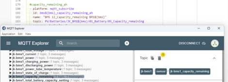
When setting up the individual BMS ESPs, i decided to check is the generated MQTT topics matches what i could find in your code, and thats where i got confused, because none of the topics seems to match as i expected it to?
I am definitly no expert, so maybe i have misunderstood what code the BMS ESPs should run, or the naming or something else :)

I've attached an image what im looking at when comparing the topics for Capacity remaining.
 

Attachments

  • Skærmbillede 2024-03-13 215406.png
    Skærmbillede 2024-03-13 215406.png
    60.6 KB · Views: 11
Well scratch that update. Seems the ESP is rebooting or something about every 22 minutes. Ran for hours without issue. Get comms failure with battery, no data to HA, and the website on the ESP itself is not available for about 7 minutes.

All charging and discharging stops when this occurs.
Well back to trying this project again. I reflashed and now it’s working fine. No battery disconnects. Will let it run and monitor.

One question, when you enable ForceBulk in HA is the inverter supposed to go into charge mode or is this the setting to keep it up to bulk absorbtion setting when already in a charging state?
 
@Der_Hannes i'm looking at your multi bms solution for MQTT, and today i finaly got some hours to play around.

As i understood, the ESPs for each bms should use the standard code from "syssi/esphome-jk-bms", and the esp-can-controller, will then subscribe to the topics generated from each bms.

When setting up the individual BMS ESPs, i decided to check is the generated MQTT topics matches what i could find in your code, and thats where i got confused, because none of the topics seems to match as i expected it to?
I am definitly no expert, so maybe i have misunderstood what code the BMS ESPs should run, or the naming or something else :)

I've attached an image what im looking at when comparing the topics for Capacity remaining.
nice too hear you are interested

You are absolutely right with your understanding
well, i have heavily modified my jk-bms topics to suite my common mqtt structure - thats why the default topics does not match.
Please excuse, i was not able yet to push my JK Configuration into an Github Repo in case someone wants to follow my custom topic-structure.

So you would have to change all topics in the yaml file to the topics where your values are published to your broker

i know thats a lot of work to do - but if your BMSs follow the same logic, it has to be done only once for the template file sensors_jk_bms.yaml
For your example topic it would be
topic: jk-bms${bms}/sensor/jk-bms${bms}_capacity_remaining

The variable ${bms} will then be replaced by the parameter you provide when including the template (for your example "1") and can be used in topic, state_topic and name as you wish. But the id should be left untouched
topic is where to subscribe
state_topic is where the value gets published then by the ESP
 
Last edited:
One question, when you enable ForceBulk in HA is the inverter supposed to go into charge mode or is this the setting to keep it up to bulk absorbtion setting when already in a charging state?
If this switch is turned "ON" it prevents from going into Float mode after absorbing - the charge mode stays on bulk then
 

diy solar

diy solar
Back
Top