diy solar

diy solar

YamBMS JK-BMS-CAN with new Cut-Off Charging Logic (open-source)

@chaosnature, the S3 lite has been tested internally (both wired and wireless versions) with the latest YAML code.
There's a separate folder in the GitHub repo called 'config' - you'll find the S3 lite instructions there.
Follow those, adjusting the main YAML as instructed and it should work for you.
Thanks
 
I just got the M5 CAN hat and hope to set it up soon on Bat02.

I just hit OVP again (once today) and for the cell that hit OVP at 3.55V, it came down at roughly 3.42V in less than 240 seconds.

So it's not a whole lot of "slow down" in terms of Ah etc that is needed (at least on that specific cell).

Very roughly:
2A balance (JK BMS) * 50% duty cycle of balancer * 240s/3600s < 1 Ah
 
I followed the instructions - set AoBo and SMA it detected the battries only after settings it physically at the inveter
and then it does di charge for few seconds then stopped
1711035608168.png

Now the energy just leaks to the grid

1711035683941.png
 
I followed the instructions - set AoBo and SMA it detected the battries only after settings it physically at the inveter
and then it does di charge for few seconds then stopped
View attachment 203459

Now the energy just leaks to the grid

View attachment 203460
Just so i am sure i did the correct thing - i changed both the CanBus Name and Canbus protocol to SMA , though it only mentioned to change the CANbus protocol as per the instructions.

am i right to change both ?
 
Just so i am sure i did the correct thing - i changed both the CanBus Name and Canbus protocol to SMA , though it only mentioned to change the CANbus protocol as per the instructions.

am i right to change both ?

In the update post, I stated to change both to SMA (if you are using a Solis inverter.
Final note, for any users using this code with a Solis inverter, I recommend setting the CAN protocol and CAN BMS name to 'SMA', then setting the battery name to 'AoBo' on the inverter itself.

On the ESP32 settings, set both to SMA. On your inverter, set the battery name / type to 'AoBo'.
 
In the update post, I stated to change both to SMA (if you are using a Solis inverter.


On the ESP32 settings, set both to SMA. On your inverter, set the battery name / type to 'AoBo'.
O.k thats what i did..

Anyone else with my brand Solis can confirm this workson SMA?
 
And does the inverter have an alarm, saying something like 'BatName'?
If it doesn't, that suggests that the CAN connection is working as expected.
 
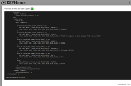
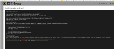
The other issue i am having is , flashing the second ESP is failing though the code pass validation
1711041876981.png

1711041942075.png
 
And does the inverter have an alarm, saying something like 'BatName'?
If it doesn't, that suggests that the CAN connection is working as expected.
yes it did say BatName fialure...then i changed the name to AoBo on the inverter again (though it was already changed over the app b4) and the error cleared
 
yes it did say BatName fialure...then i changed the name to AoBo on the inverter again (though it was already changed over the app b4) and the error cleared
This code is running on two Solis inverters that I manage with no issues.
I prefer local configuration changes on the inverter itself. Using an app means you're relying on a remote server to pass those changes through correctly, and it doesn't always work as quickly as hoped.
 
This code is running on two Solis inverters that I manage with no issues.
I prefer local configuration changes on the inverter itself. Using an app means you're relying on a remote server to pass those changes through correctly, and it doesn't always work as quickly as hoped.
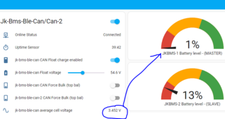
It works perfectly on Pylon selection and i already see the improvement, not sure what was coded but i see absolutely no leaks to the grid compared to the previous versions.
but soon as i change it to SMA and change the inverter to AoBo it stops.
 
reverts to wireless ??? you have it wired ????
Hi Silverstone

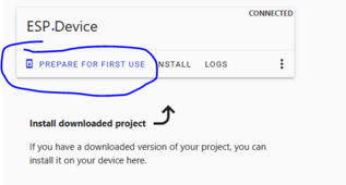
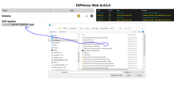
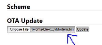
what i mean to say is the only way i could flash the S3 using ESPHome; is to flash "Prepare for first use" first, connect to my Wifi, compile the yaml and then upload as below
1711047526523.png
1711047413165.png
 
How do you get this to show up? I don't see that on mine (running previous version).
1711047941115.png
 
Hi Silverstone

what i mean to say is the only way i could flash the S3 using ESPHome; is to flash "Prepare for first use" first, connect to my Wifi, compile the yaml and then upload as below
View attachment 203498
View attachment 203497
Uhm ... Maybe a bug maybe a feature.

I'll have to try my Atom S3 Lite as well. But remember that sometimes it might be necessary to change the device type and also the STACK SIZE.

I was particularly confused because I was thinking (I have some ESP32 with Ethernet ... not yet in use though) that your ESPHome reverted from WiFi to Ethernet. Then I thought that you meant "reverting from BLE to Ethernet" (or viceversa) 🤣.

Sorry, bad day for me
No worries - we all have one....
 
min battery voltage based on BMS value
This is close to the feature i was hoping to receive through one of your updates.
Where BMS 0% SoC Equal to Inverter Overdischarge SOC - So that when the system hits inverter Overdischarge SOC it stops.

but i understand why you would not implement this, the BMS 0% SoC is supposed to stop the discharge, but i have still fighting with getting this configured after many days of allowing it to settle between the 2 extremes...
I thought there was an "offset" parameter (typically 0.0-0.1V) between inverter and BMS. Or was that only for charging ?
 
Did the minimum cell voltage hit 3.32v at any point?
If not, that suggests that your battery capacity as set in the BMS itself is not quite accurate.
o.k Growatt Datasheet advised its a 95 Ah battery capacity , so maybe it has degraded over time, therefore i need to keep adjusting
 

diy solar

diy solar
Back
Top