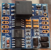
Before trying this, make sure you have exhausted other things first.Concerning the canbus boards @shvm received boards with reversed tx and rx, to test.
Like, soldering proper headers to the pads (if they aren't already) on the CAN transceiver board. Just pins in contact on a breadboard will probably won't work due to high-speed nature.

 .
.


 )
)