diy solar

diy solar

Will this work for pre-charging inverter capacitors?

I just updated the resource with a template of the lable that can be printed from Adobe PDF reader and fit the Perco switch.
 
So I have Com connected to battery and 2 connected to positive bus where the inverter is also connected. Off is off for everything . Yes?
 
Yep.... Off is for everything in your case. You have it wired more as a battery disconnect......Maybe I should add a label for battery disconnect to the file.
 
I have the DC side of my electrical system completed and am waiting on parts for the AC distribution. I would like to energize my system and do all the set up on solar charge controller, battery protect, Multiplus 3000 and BMV 712 smart. My question is how do i discharge the capacitors of the Multiplus before connecting the AC distribution side of the inverter? Thanks
 
My question is how do i discharge the capacitors of the Multiplus before connecting the AC distribution side of the inverter? Thanks

Not sure why you need to do this, but I usually just have some load on the AC side, then disconnect the DC side and leave it like that a few seconds. Things I have used as a dummy load:
- 60W lamp
- Hair dryer.
- space heater
 
Not sure why you need to do this, but I usually just have some load on the AC side, then disconnect the DC side and leave it like that a few seconds. Things I have used as a dummy load:
- 60W lamp
- Hair dryer.
- space heater
Victron Inverters have to be hardwired, there is no place to plug in a load. I don't want to get shocked trying to hardwire the breakers and AC circuits. I will disconnect the DC side before beginning but the caps will be holding a charge....
 
It's generally required that the capacitors self discharge within 5 to 10 minutes. I'd be very surprised if Victron stuff didn't follow that UL rule.
 
It's generally required that the capacitors self discharge within 5 to 10 minutes. I'd be very surprised if Victron stuff didn't follow that UL rule.
Oh! That's great to know and simplfies things aot. Thanks for your help
 
Victron Inverters have to be hardwired, there is no place to plug in a load. I don't want to get shocked trying to hardwire the breakers and AC circuits. I will disconnect the DC side before beginning but the caps will be holding a charge....
I see. Thinking back to when I did mine I trusted the on-off switch on the Victron. So initial hookup for testing (and final) went like this:
  • Cover off, power switch off. confirm switch. Nothing connected to Victron
  • Hook up DC +, Using a 20Ω resistor, hook up DC - by hand (holding resistor in series with DC line and terminal. Hold a few seconds, remove, and properly (tighten down terminals) hook up DC-
  • Confirm on-off switch is off. I did this obsessively several times.
  • Hook up AC load properly, while checking on-off switch obsessively
  • Turn on-off switch to on.
In hindsight, I should have disconnected the DC, waited, and check with a multimeter on the AC side to confirm 0V.
 
I am building a removable battery pack for my van RV (it gets much hotter than is conducive to a long battery life here in Phoenix and I want to be able to store the battery in an air conditioned space in the summer when not using the van). To make this less of a a pain in the rear to do, I built a 200A battery disconnect switch and a 100ohm, 12.5W resistor into my battery pack. The switch has two marked positions. Precharge (open) and Run (closed). I have a circuit breaker elsewhere that I can use if I ever need to manual disconnect the battery without having to unplug it.

Process to follow before plugging the battery into the inverter (Multiplus 24/2000):
  • Turn off the inverter.
  • Set the switch to the precharge position.
  • Wait 10 seconds.
  • Set the switch to run position.
  • Turn on the inverter.
Even if I turn on the inverter with the battery switch in the precharge position nothing bad will happen. The inverter will turn itself off when the supply voltage drops below the low voltage disconnect threshold, but even if it didn't happen, the resistor is sized so that it won't smoke even if the positive output of the battery pack is shorted to ground (the resistor would be dissipating 6W of heat which it can do continuously). There is a 175A fuse built into the battery (plus the 150A BMS) to take care of a shorted output with the switch in the run position.

I am using this chassis mount resistor. It only costs $3. I am bolting it to one of the water cooled chill plates so heat dissipation should not be an issue.


Attached is a copy of my latest system drawing. The battery precharge circuit is on page 2.
 

Attachments

  • VanPower11.pdf
    321.4 KB · Views: 25
Last edited:
I see. Thinking back to when I did mine I trusted the on-off switch on the Victron. So initial hookup for testing (and final) went like this:
  • Cover off, power switch off. confirm switch. Nothing connected to Victron
  • Hook up DC +, Using a 20Ω resistor, hook up DC - by hand (holding resistor in series with DC line and terminal. Hold a few seconds, remove, and properly (tighten down terminals) hook up DC-
  • Confirm on-off switch is off. I did this obsessively several times.
  • Hook up AC load properly, while checking on-off switch obsessively
  • Turn on-off switch to on.
In hindsight, I should have disconnected the DC, waited, and check with a multimeter on the AC side to confirm 0V.
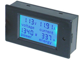
Your comment has me thinking about adding one of these to the AC output side of my Inverter.


I am using a pair of the DC versions of these to measure my DC loads.
 
Do as you like but bolting a resistor that will only be in circuit for 10 seconds to a cooling plate?
 
Do as you like but bolting a resistor that will only be in circuit for 10 seconds to a cooling plate?
The cooling plate is inside the battery pack for other reasons. Why not use it?

Plus I am an engineer. I expect idiot users to not do things right. And that description includes me.
 
I am building a removable battery pack for my van RV (it gets much hotter than is conducive to a long battery life here in Phoenix and I want to be able to store the battery in an air conditioned space in the summer when not using the van). To make this less of a a pain in the rear to do, I built a 200A battery disconnect switch and a 100ohm, 12.5W resistor into my battery pack. The switch has two marked positions. Precharge (open) and Run (closed). I have a circuit breaker elsewhere that I can use if I ever need to manual disconnect the battery without having to unplug it.

Process to follow before plugging the battery into the inverter (Multiplus 24/2000):
  • Turn off the inverter.
  • Set the switch to the precharge position.
  • Wait 10 seconds.
  • Set the switch to run position.
  • Turn on the inverter.
Even if I turn on the inverter with the battery switch in the precharge position nothing bad will happen. The inverter will turn itself off when the supply voltage drops below the low voltage disconnect threshold, but even if it didn't happen, the resistor is sized so that it won't smoke even if the positive output of the battery pack is shorted to ground (the resistor would be dissipating 6W of heat which it can do continuously). There is a 175A fuse built into the battery (plus the 150A BMS) to take care of a shorted output with the switch in the run position.

I am using this chassis mount resistor. It only costs $3. I am bolting it to one of the water cooled chill plates so heat dissipation should not be an issue.


Attached is a copy of my latest system drawing. The battery precharge circuit is on page 2.
Being 4 hours south of you, I am essentially in the same boat. I have my batteries in a rack made by Overkill Solar and they connect to a master Perko battery switch with Pre-charge, as designed by Filter Guy. My battery pack comes out with the disconnection of the +/- cables. Do you use your inverter for AC pass through when your battery is out of the van, a question because if not, your inverter was turned off when you removed your batteries, no? Your plans, as noted before, are a thing of beauty.
 
Back
Top