diy solar

diy solar

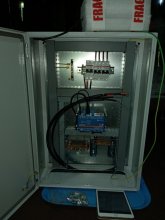
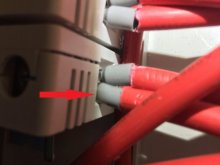
Is this string box wired correctly?

Closer to 11awg (4.17mm^2) & 90°C insulation. I wouldn't have any qualms about running this @ 30A provided the voltage drop is acceptable.
"Acceptable" That's a nice word. My goal is to reduce the voltage drop (energy loss) as much as possible within reason. I'm not spending thousands of dollars just to lose 10% of my electricity before it even gets to my charge controller. For me a 2-3% loss is acceptable.
 
"Acceptable" That's a nice word. My goal is to reduce the voltage drop (energy loss) as much as possible within reason. I'm not spending thousands of dollars just to lose 10% of my electricity before it even gets to my charge controller. For me a 2-3% loss is acceptable.

Agree. 2-3% is acceptable. What is the distance from the combiner box to the battery?
 
Your combiner box is really pushing it trying to handle 30A (4s3p) with the wires and the MC4 they are using, MC4 connector max currating is 30A (UL rated at 20A).
The wires in your pcitures are the right type for solar application but only 12AWG (4mm).
I cannot read Spanish:
Actually, here is the brand of wire they've included:

I'm not sure exactly which product. I've got a 1x4mm2 wire rated to 90 degrees. It's clearly a "Solar Fotovoltaico" but the table for the product measures the wires by AWG and my cables say 4mm2 on the side. As Snoobler said, 4mm2 is close to 11AWG, than it is to 12AWG.

If this is the product (12AWG): https://www.elcope.com.pe/wp-content/uploads/2019/02/CABLE-SOLAR-FOTOVOLTAICO.pdf
It says Current capacity (Air) = 40A; Current capacity (Duct) = 30A
 
Last edited:
Agree. 2-3% is acceptable. What is the distance from the combiner box to the battery?
It depends how I organize my wall.
One thing is the distance from combiner box to battery.
Another thing is the distance from combiner box to MPPT. Isn't the latter measurement more important here?

Combiner box to battery bank distance will be approximately 2.5m (8.2ft.)
Combiner box to MPPT will be less, depending on the arrangement of wall. There are some space constraints involved. Here is an image of the space. https://diysolarforum.com/threads/o...se-help-design-my-solar-component-wall.20832/
From floor to horizontal steel beam is about 2.5m, and the wide space between the two aluminum vertical supports measures 65cm wide.

The way they've designed the system is that everything basically feeds into this cabinet that measures 50cm wide x 70cm tall x 20cm deep
 

Attachments

  • 20210404_090523.jpg
    20210404_090523.jpg
    92.6 KB · Views: 7
It depends how I organize my wall.
One thing is the distance from combiner box to battery.
Another thing is the distance from combiner box to MPPT. Isn't the latter measurement more important here?

Yes, sorry, that's what I meant.

For the individual strings, assuming 100', only 2.1%:


Combiner box to battery bank distance will be approximately 2.5m (8.2ft.)

Let's just assume combiner box to MPPT is 8.2 ft.

1.3% @ 48V (Voltage will be higher most of the time, so this is conservative), 30A


Combiner box to MPPT will be less, depending on the arrangement of wall. There are some space constraints involved. Here is an image of the space. https://diysolarforum.com/threads/o...se-help-design-my-solar-component-wall.20832/
From floor to horizontal steel beam is about 2.5m, and the wide space between the two aluminum vertical supports measures 65cm wide.

I find a voltage drop from the array of 2.1% over 100 ft acceptable.

I find an additional 1.3% voltage drop from the combiner to the MPPT over 8.2 ft acceptable.

If I REALLY cared, I'd get a 8awg MC4 to plug into the combiner box and run to the MPPT to "shorten" the 10awg/30A run to a few inches.
 
When these 3 panels are in series, they produce around 160 volts, with 10 amps in each string.

Another thing I’m seeing is the gang box connectors for what I think is the combiner, but could be something else, aren’t those rated for 60 amps? Not sure of the voltage. There's potential for 10 amps at 160 volts entering in each of the three strings and leaving a combined 160 volts and 30 amps headed to the SCC.

I'm also curious about the fuse holders. They are combined by using two wires in each to create a Daisy chain to combine them. I don't know if this is an accepted practice. I'm doing something similar this weekend with 12 gauge wire and a 3 amp circuit, but just like my comment above, there could be 30 amps coming out of the fuses after combined.

With 11 or 12 Gauge wire, although it is acceptable, that exceeds my comfort level when combined, and I would want to go to 8 AWG. I would also not use MC4 Connectors, but you can get an Amphenol H4 Connector for AWG wire rated to 45 amps. I do wonder if the 8 AWG MC4 connectors are rated higher than 30 amps.
 
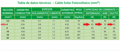
I contacted the manufacturer and they sent me the technical specifications of the wires in my photos. Hard to believe really.
55amps air&ducts?!

I asked if this was verified by a third party and at what distance of wire is it capable of transferring this current without incurring more than a 2% loss.

If these specs are true, then I guess the only weak link left are the output MC4 connectors. But maybe those are rated higher than what you all
might assume.EspecificacionesdePVcable4mm2.png
 
Last edited:
Yes, sorry, that's what I meant.

For the individual strings, assuming 100', only 2.1%:


Let's just assume combiner box to MPPT is 8.2 ft.

1.3% @ 48V (Voltage will be higher most of the time, so this is conservative), 30A


I find a voltage drop from the array of 2.1% over 100 ft acceptable.

I find an additional 1.3% voltage drop from the combiner to the MPPT over 8.2 ft acceptable.

If I REALLY cared, I'd get a 8awg MC4 to plug into the combiner box and run to the MPPT to "shorten" the 10awg/30A run to a few inches.
So what are my options here?
A) Replace the 30A MC4s that are currently on the box with 8AWG MC4s and replace the 4mm cables on the output with 10AWG cables?
B) As chrisski said: Replace the current MC4s with Amphenol H4 connectors
C) Could I just eliminate the output MC4s, and not use any MC4s nor H4 connectors for the output? I would just restring wire from the outputs of the fuse holders to whatever length I need to connect to the MPPT?
D) Leave everything the way it is. I'm not sure if this is OK though. Given that the MC4s are only rated for 30A, and another forum member said that they are only UL rated for 20A! At some point it looks like there will be more than 30A going through those connectors, because the Isc of my panels is 10.61

As a reminder, the panel configuration is 4s3p.

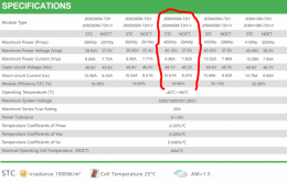
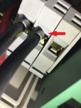
To clear up any doubts, here are the specs of the panels. Also, I'm going to include pictures of the wire connections coming out of the fuse holders (you can also see these from further away in my previous pictures on the first page of this thread) that I would need to remove, and then reattach with a longer length of wire to reach the MPPT if I were to choose option C).

400wpanelstats.PNGIMG_2540.JPGIMG_2547.JPGIMG_2540.JPGIMG_2547.JPG
 
For box entry, instead of MC4, I use Cable Glands, Based on wire size. They’re watertight, with the same rating as MC4, but I add a little RTV at the leakpoints. In America, about 50 cents each from Amazon.
 
For box entry, instead of MC4, I use Cable Glands, Based on wire size. They’re watertight, with the same rating as MC4, but I add a little RTV at the leakpoints. In America, about 50 cents each from Amazon.
Cable glands? Aren't those for penetrating a roof?

It sounds like maybe I haven't understood why they're using MC4 connectors in the first place for the string box. Is that to keep out the elements?

In my situation I'm going to run the PV wires through the roof down to the string box located INSIDE my house.
 
I always thought the prebuilt boxes used the MC4 to make attachment easy for the end user.

I use cable glands when wires penetrate something that needs to be secured and or waterproof. My combiner box inside has them to keep the wire secured from being pulled out of the circuit breaker.
 
I always thought the prebuilt boxes used the MC4 to make attachment easy for the end user.

I use cable glands when wires penetrate something that needs to be secured and or waterproof. My combiner box inside has them to keep the wire secured from being pulled out of the circuit breaker.

In my situation, I don't see what the point of the MC4 connecters are. Maybe you can enlighten me? Someone on this thread said they limit the current to 30A. Given that the cable itself is supposedly rated for 55A why not remove the MC4s and just run the pure cables to the PV inlet on the MPPT?
 
Last edited:
It sounds like maybe I haven't understood why they're using MC4 connectors in the first place for the string box. Is that to keep out the elements?

That's a good question. Convenience? It seems to me that running a cable through a gland on the side of a box is less prone to problems since it's justs a pass-through without any crimps involved. If I were to use a combiner box, I think I would go the gland route instead of MC4.
 
That's a good question. Convenience? It seems to me that running a cable through a gland on the side of a box is less prone to problems since it's justs a pass-through without any crimps involved. If I were to use a combiner box, I think I would go the gland route instead of MC4.
OK, this is good feedback.

In my case, the MC4s just seem like a limitation.
 
I didn't need to use a combiner box since my string is only two panels in series. After the MC4 connectors on the panels, my PV wire makes a complete run across the roof of the RV and down into the component area to the circuit breaker. No breaks.

If I had multiple parallel strings, it would make sense for me to combine them on the roof, either with a Y connector or a combiner box, and then come off the roof with just one pair of heavier gauge wires.
 
n my situation, I don't see what the point of the MC4 connecters are. Maybe you can enlighten me? Someone on this thread said they limit the current to 30A. Given that the cable itself is supposedly rated for 55A why not remove the MC4s and just run the pure cables to the PV inlet on the MPPT?
No reason you can’t remove the MC4. If that were my situation, I’d remove the MC4 cable. Where the cable enters the box I’d either put a Split loom or Cable gland for protection.
 
No reason you can’t remove the MC4. If that were my situation, I’d remove the MC4 cable. Where the cable enters the box I’d either put a Split loom or Cable gland for protection.
Okay thanks for confirming. That's probably the easiest fix.
 
I didn't need to use a combiner box since my string is only two panels in series. After the MC4 connectors on the panels, my PV wire makes a complete run across the roof of the RV and down into the component area to the circuit breaker. No breaks.

If I had multiple parallel strings, it would make sense for me to combine them on the roof, either with a Y connector or a combiner box, and then come off the roof with just one pair of heavier gauge wires.
How does that end up being more economical for you? Thicker gauge wire being run at a longer distance.
 
Back
Top