diy solar

diy solar

NI-FE 1000ah 12V with 5kw of panels running 4kw Reverse Cycle AC for heating house

jimbo78

New Member
Joined
Dec 14, 2019
Messages
74
Location
Melbourne, Australia
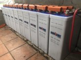
-Nickel-Iron (NI-FE) 1000ah 12V (12kw of usable storage)
-5kw of panels
-4kw Reverse Cycle AC for heating and cooling (~900w electrical power)

Hi everybody,
I have been busy building my solar system which is primarily designed to heat my house in the winter. I initially looked at lithium-based battery tech but decided against it which I will go into in later posts. I’m located on the outskirts of Melbourne Australia, so we have quite a mild climate here compared with many places in the US. The worst month is July with an average temperature of 7-14C (45-57F). Previously I was heating my house with wood and I would consume around $1400 of wood per winter.

This system at this point is experimental as I was not sure what to expect with the Nickel-Iron battery technology, but 5 months in I’m very comfortable with the technology and I thought a bunch of you guys would also be very interested. I will go into specifics of my system, I have collected a lot of data of my system from the very first cycle up until now (see below). I have only needed to light the fire once since switching over for heating mid-August, the system is not large enough to run 100% of the time, but if I only need to burn wood less than 10% of the time in the middle of winter then it’s a win in my book. I also expect to be able to upscale this system for 100% heating in the future, and I will go into how I intend to do that also.

I will also say that there is a lot of negativity and doubt around NI-FE as a useful technology. Sure these batteries may not be as “Turn key” as some others, but I don’t think they are as bad as many try to make them out to be. All batteries require some amount of supervision and maintenance even if its just dusting them off and/or re-buying them once they are spent. I look at my batteries as family heirlooms and I expect them to not only outlive myself but I fully expect to hand them down.

Overview of my systems data so far.

MonthSource (kWh)Load (kWh)Batt Out (kWh)VoltageCyclesROI
July26.0224.9922.1116.07 - 10.246.15$7.40
August228.49169.30133.1716.77 - 10.0220.35$47.81
September288.38224.36140.2016.72 - 9.9915.28$68.63
October366.55295.02134.9116.75 - 10.6313.10$92.90
November326.65243.7671.0916.96 - 10.4612.78$80.73
December81.3049.2322.3716.31 - 12.555.29$16.67

Totals
Source 1317.39kWh, Load 1006.65kWh

Battery Voltage Range
Min 9.99V, Max 16.96V

Battery Cycles
72.95

Return On Investment
$314.15

So, over the coming weeks I will be posting pictures and details of my system so far, why I choose this route, my mistakes so far, and where I intend this system to go into the future. Along the way I’ll be happy to answer any questions you may have so please ask away however I will be posting my main topics first which may cover many of your questions. Once the main posts are covered I’ll then focus on any specific questions that were not covered.
 

Attachments

  • IMG_7291.jpg
    IMG_7291.jpg
    72.1 KB · Views: 141
If you have the space for them, NiFe is a great choice. Damn near indestructible, rebuildable...
what heating system do you have?
 
So, let’s start with the solar panels (yeah, I know boring right). As this is an experimental system, I decided to build my own ground mount. I had steel angle cut to length at my local steel shop which probably cost me around AU$300 (these are plantation oz store tokens). I drilled out holes and used galvanized bolts to fix it all together. I decided on an angle of 45deg with optimal angel being around 38deg. I did this because of ease of construction and its biased towards winter which is important for my main use case. During summer we have an abundance of sun so I’m not concerned with summer efficiency. If you would like to see the plans for the ground mount let me know and I will post them. I purchased commercial solar rail to mount the panels, this cost me just over AU$700 so all up my ground mount was just over AU$1k.

SwapOut.jpg

Next, I needed to purchase some solar panels, this is where I made my first mistake. I purchased 8 cheap crappy (RICH solar) panels off eBay (specs in pic). Luckily, I could not purchase more crappy panels to complete my solar array, and rather than having a hodgepodge of panels I decided to purchase quality panels (specs in pic as well). Note that any cheap panel calming 1200w/m2 is bogus, the industry standard is 1000w/m2, many eBay suppliers will not post that number and will refuse to post or send a pic of the specifications on the actual panel. If your purchasing panels that should be a major red flag to you. I purchased 16x 315w name brand panels (JinKo Solar) which have a decent warranty and reputation, for a total of (and a genuine) 5kw array. Total cost was just under AU$4k so all up my ground mount and panels cost AU$5k.

CrappyRichSolar.jpgJinkoSolar.jpg

By this time, you’re probably wondering how I get 5kw of power into a 12V system right? The amperage must be off the chart? Well I am limited by my charge controllers and I will get to that in a future post, but I have way over-specced these panels to allow me to get a full charge in cloudy wintry conditions. We get a lot of overcast days and panels these days are so cheap I decided not to skimp out in this area. Also, as I upgrade my system, I won’t need to touch my panels as I have more than enough spare capacity as I go from 12V to 24V and eventually 48V.

SwappingOut.jpgFinishedArray.JPG

Bird poop has become a problem, as the birds love to sit on the top frame of the panels and leave their deposits below. I attempted to try and solve this issue with a plastic pest barrier, however that’s been a significant failure so far.

BirdPoop.JPG
 
Keeping a certain bird off structures isn't as easy as you might think. These birds knock out mobile (cell) phone transmitters amongst other things.

 
The next part of the system is the charge controllers. Currently I’m using Epever charge controllers and for the most part I’m quite happy with them however I do have a few issues which I will go into. My main charge controller is the Tracer10420AN which has a Max PV voltage of 180-200v Max current of 100A and works with 12/24/36/48 volt systems. So, as I upgrade my system, I intend to go from 12 to 28 then to 48 volts and the investment into my charge controllers is well worth it as I won’t need to replace the equipment when I change voltage (unlike my inverter). The battery voltage range in 12v mode is quite wide 9-17v which is great for NIFE batteries however a custom charging profile is going to be necessary and the Epever controllers can accommodate that quite well. If your purchasing an Epever controller I highly recommend you purchase a MT-50 remote display which also allows you to program all settings. There is a laptop and mobile app however I was not too impressed with either of those.

IMG_7293.jpgIMG_6904.jpg

The cost of Epever charge controllers is quite reasonable, the 200V100A model I have cost me AU$700 which is about half the cost of an equivalent Victron controller. Now I need to talk about the 200lbs gorilla in the room, Voltage Drop! As you know I’m running a 12V system, because the voltage is so low voltage drop is a big deal and I knew that going in. There are some changes I will make going forward but also, I’m planning on upgrading to a 24v system which will obviously help longer term.

First as you can see (in my original post) the battery bank is quite wide and I have my controllers off to the side. I’m running 70mm2 wire with the negative wire being 5m in length and the positive being 2m in length. That’s not ideal and oversizing the wire didn’t eliminate the issue. At 80A I have around 0.5V of drop, so if your controller is outputting 17V the batteries are only seeing 16.5V as the current drops however (as the sun goes down) the batteries will see up to 17V and for other battery types this is a big problem, but for NIFE no worries some suppliers recommend 19V to start with or even connecting a 12V panel directly to the battery without a controller. All it means for NIFE type batteries is how much off-gassing will be produced (hydrogen) and a little more maintenance required, the batteries can’t be seriously damaged though over volt scenarios.

Although the system is running in its current state, I’m not happy with the amount of voltage drop I’m seeing. I was able to use the remote voltage sensing feature of my 100A controller which works quite well. I purchased an extra temp sensor, cut off the temp sensor and used the remainder of the wire (adding an extension) to go across the battery and plugged it into the remote sensing port which is the same plug as the temp sensor port. When I upgrade to 24V I will have a 2nd bank of cells in front of the first bank and I’ll bring the charge controllers a little closer. I hope to get the 70mm2 wires to under 1m in length and there will also be a short length at the other end of the bank making the series connection between the 2 banks giving 24v (20 cells).

I have designed this system around my reverse cycle AC which draws around 900w of electrical energy. So lets just round that up to 100A at 12V. Ideally I’d like to be able to run my load while also charging my batteries so 200A is what I have been targeting. Even when I go to 24v, 200A is still useful as that’s 5kw which means I’ll be able to make full use of my panels in good sunlight so 200A is still worth targeting short term. One of the reasons I chose Epever AN series is it has parallel capability but until now the module (PT-ADP-PORT PT Adapter) required to do paralleling has not been available, but in writing this post I finally see its available on eBay!! So, I’ll have some further experimenting to do in the new year!! I will keep you all up to date on my paralleling experiences!

https://www.ebay.com.au/itm/PT-ADP-PORT-PT-Adapter-Adjust-The-Epever-Tracer-AN-Controller-In-Parallel-Use/352895361313?ssPageName=STRK:MEBIDX:IT&_trksid=p2060353.m1438.l2649

So far my paralleling experience has not been great, I have 2 mismatched controllers as the smaller controller (Epever 40A 100V PV Tracer 4210AN) is cheap and I just wanted to see how they behave together. In the end they seem to punch on more than they benefit the system, with only low battery scenarios where they both seem to play ok. I’m sure my voltage drop has a lot to do with it, and I may be able to avoid those issues if I ran separate wires back to the batteries. But that gets expensive and I decided it was not worth it. Since the parallel device is now available that’s the route I need to take in order to achieve 200A. My PV array is configured into 2 strings, 3x 4 Panels in series giving 132v 28A and 2x 2 Panels for 66v 18.8A. Once I purchase my 2nd 100A controller I will run 2 even strings 2x 4 panels giving 132v 18.8A each.

One other issue I have is with my charge controller’s behavior when I put a load on my Inverter, but I will get into that in my Inverter post.
 
Last edited:
Next, I want to talk about fuses, this was another mistake I made, purchasing a 300A fuse/isolator off eBay in order to isolate my batteries, what could possibly go wrong? Totally legit right? Its say 300A so it must be true!

58572776596__30899A06-FFDF-417D-8159-4A82CFF7C0FA.JPG
Well basically I would hit about 80A continuous and this thing would heat up and click off. So obviously I needed a serious solution and not a toy off eBay, I should have twigged with the terminal sizes but I have used these before on my camping setup and although the espresso machine (did I say camping? I meant glamping) would trip it, it otherwise worked OK. But this is when I decided to no longer purchase crap off eBay and engage my local solar shop. They suggested the solution below and the fuse alone (not including the housing) is almost twice the size as that toy off eBay and this type, NT1 HRC goes up to 300A which is great as I’m targeting 200A. There is a smaller version NT0 HRC however that tops out at 160A.

58606766120__AF463942-1419-4D54-9CC4-7FA20A260F5F.JPGIMG_7298(1).jpg

The fuses themselves are around AU$13 to buy and the housings are AU$140 each and each hold 3 fuses. In the end I will only really need 3 fuses, but I decided to have 2 housings in order to separate my Inverter from my charge controllers. This was done because my original inverter didn’t have the voltage range required by NI-FE batteries. I’ll go into the inverter side in a future post. But really all I would need for this system as it stands now and into the future is 3 fuses, 250A for the positive rail, 250A for the charge controller negative, and 160A for the Inverter negative (1200w max) which can be increased as I upgrade my inverter in future. Opening the housing disconnects the fuse from both sides, this is very important as you must not short any lead from these batteries. That’s very dangerous (especially with hydrogen around), so these fuses are used for both fusing as well as battery isolation. Total cost here was around AU$250 and well worth it for peace of mind.

IMG_7300.jpg

Next, I needed a way of collecting data from my system and although there are systems out there to do that I decided to roll my own. I have a raspberry Pi Zero which has an inbuilt WiFi chip I added a Analog to digital converter board (ads1115 16bit precision) which does all the sensing for both voltage and current. I’m running standard raspbian and added the NodeJS package where I have my custom script that takes the Voltage as well as the Current from 2 Hall effect sensors (one for the charge controllers or source side and the other for the Inverter or load side). Hall effect sensors allow me to not include a shunt along my main battery bus. Shunts are basically a large 0.25ohm resistor, and any resistance adds to voltage drop. As you know that’s been a huge problem especially for lower voltage systems, so I decided to be proactive here. The down side however is hall effect sensors are not so accurate at low amps, so my system tends to over report low usage. I don’t care about that so much, what I really want to monitor is kwh’s in and kwh’s out and they do a great job at that.

So far, I have over 99.9% of the data, I had a bug early on where I probably lost almost a day of data. I also loose data if my Wifi or my website goes down, that’s an issue I need to fix but I haven’t had too many outages so far. The ADC takes 860 samples per second and I take a sample every second. Once 10min has passed I average out all the samples and upload the average for each. So, I keep track of data at a resolution of 10min however that’s made up of thousands of samples over all. Once the data is up to my website, I can slice it hourly, daily, weekly, monthly or even yearly. In my very first post you can see the monthly view of the data. This will become important in future posts when I get into the specifics of the cycles of these batteries. I don’t just have my experiences I also have some very accurate hard data to back up my experiences as well.
 
Last edited:
I finally have my 2 Epever charge controllers acting in parallel together using the PT-ADP-PORT! There is both good and bad here, and the bad starts with a very poorly written manual that skips the most important step of all, it also includes a bunch of unnecessary steps. The software that is available is abysmal, the one device that I really like namely the MT-50 does not work when these controllers are connected in parallel, this is a real shame I was hoping to see 200A on the screen along with an overview of the entire charging system. However, the MT-50 is still useful as you can still use it to configure the controllers individually while the controllers are not connected together. This is a far better approach than using the god-awful software.

IMG_7528.jpg

Just a note on the god-awful Epever windows software, if you ever get the message on the com port (Doesn’t exist or not yet set up), and you will get it if you simply use the Add Station button. You need to go into the Port Config menu, Port Configuration, and hit the Add button on that screen with the correct port selected!!!! I’ve probably waisted 2 hours of my life installing drivers and playing with port setting in device manager only to find out its their shitty software and not my settings! ARG! I hope I save at least one of you from pulling your hair out.

The good news however despite their manual suggesting to use the windows software you can actually make this work without the software and only use an MT-50 for setting the appropriate settings for the controllers. Just remember for the MT-50 to work you have to disconnect all the controllers from each other and from the PT-ADP-PORT. Then set all your controllers with exactly the same settings. Plugging in the data cables PT-ADP-PORT Master --> CC1 --> CC2 --> etc (also the ports on the controllers are the same so it doesn’t matter which one goes to which) initilly this will make no difference to the controllers behavior. They will continue to function as they did independently. So, here is the trick, the one piece the manual neglects to mention!

You need to power cycle the controllers!!! So, Isolate the solar panels by switching them off. Connect all your data cables, then Isolate the batteries also. The controllers are now powered down. Reconnect the batteries, and switch on the solar also. Monitor the Amps for each controller and although they won’t be exact, they will both step up and down as it finds the correct point then once that’s found they will remain normally with in <1A of each other. The behavior without this function will be that one controller will be providing most of the current and the other very little. It appears that the PT-ADP-PORT does a good job at keeping the controllers balanced which also helps with the heat transfer off the controllers themselves as mine tend to get quite warm. Previously one would get quite warm and the other would be just sitting there basically idle. So all in all its working as intended, the manual and software sucks but if you follow what I have written above then its possible to get it to work.


PT-ADP-PORT

https://www.ebay.com.au/itm/PT-ADP-PORT-PT-Adapter-Adjust-The-Epever-Tracer-AN-Controller-In-Parallel-Use/352895361313?ssPageName=STRK:MEBIDX:IT&_trksid=p2060353.m1438.l2649
 
Last edited:
Ok, so now its time to start talking about the whole purpose for this thread, the NIFE batteries themselves. So, why did I choose 1000AH? NIFE batteries come in many different sizes from 10AH all the way up to 1200AH, however the most common sizes chosen is usually 200AH or 500AH. In a 48v configuration that would give you 9.6Kwh and 24kwh. My 1000AH will eventually give me 48kwh which is 100% usable (unlike lead acid or even Lithium Ion). To heat my house which is my primary purpose for building this setup, my current setup basically gives me 1 day of autonomy which is insufficient to throughout the winter months. As its currently summer here in Australia I’m hoping to purchase another 10 cells before winter, that will give me 24kwh and around 2 days of autonomy which will probably allow my system to run most of the time with maybe 10-20 days where the fire would need to be lit due to limited sun over multiple days. 48Kwh would likely bring that down to somewhere between 0-5 days max.

This is a long term (lifetime) project so I’m not only sizing the system for today I’m also sizing it for future needs. Electric Vehicles are obviously in the back of my mind and having the ability to capture the sun wile the car is out and about and then charge that car later when the sun is long gone is also something that might be handy in future. A 72V system could be handy there (60 cells) allowing ample capacity to keep an EV sufficiently charged over normal day to day use. But obviously that isn’t the only way to do it, I could create a 2nd entirely separate battery bank for that purpose. All these options are open to me, I’m not seeing any future limitations that would make me think twice about going forward with this system.

As most of you are aware, we have had some very nasty bush fires here in Australia (Jan 2020). You may be thinking why we don’t have sprinkler systems on houses in areas that are quite wooded and mostly inaccessible. Grid power is generally the first thing that goes out as its quite likely the fire burns out poles along its path. Also, when you run your sprinkler system on petrol or diesel (generator or directly), when the main fire front hits the surrounding air is starved of oxygen which kills any internal combustion engine. That moment is the critical moment when you need your sprinklers the most, and the pump just died. By the time you get it going again its too late and everything is gone along with yourself likely. Batteries however do not suffer from this issue, and you could have a generator running to keep the batteries topped up until the fire front hits, the front hits the generator dies and the batteries take over, happily run an electric powered pump all through the most critical phase. Building my battery bank into a bunker along with an emergency pump is now something I will be considering in future. Hydrogen off gassing is a concern here and that will need to be addressed in some way.

58485410878__AC0B2F6F-FAD3-4B76-95AA-748C900A19AD.JPG58486389613__0600F886-DE79-4D39-9502-E674F8434527.JPG

These batteries are made in china and are shipped empty of electrolyte allowing them to be shipped without any hazardous materials requirements as they are just plastic, nickel and iron in a wooden crate. This also reduces the shipping weight however they are still quite a heavy package. My create had a shipping weight of 485kg (just shy of ½ metric tonne) and a net weight of 441kg meaning each cell weighed 44.1kg each empty. When I got home, I put one of the cells full of electrolyte on a bathroom scale (yeah not the most accurate) and it came to 61.6kg. So, a set of 10 of these cells will come to 616kg.

Mixing the electrolyte can be quite hazardous if done incorrectly, its recommended that you mix a quantity large enough to be pored into all cells. This prevents any unevenness between cells, so you need quite a large holding tank in order to do a large bank. My supplier filled my batteries on pickup so this is not something I needed to worry about, however in around 10 year’s time or so I’m going to need to make up a large batch in order to refresh the electrolyte. I can either do that myself or possibly get someone like my supplier to do that for me if they are still around.

You can find these batteries on sites such as Alibaba and even Ebay, but you will also find sites such as https://ironedison.com/ which sells them in the US, and for me here in Australia I purchased mine from http://www.ironcorebatteries.com.au/ which was quite convenient as it turns out I was only around 1h away by road. But like anything, do your research and keep in mind how you’re going to transport these things, remember the hazardous materials requirements once they are filled with electrolyte.

IMG_7291.jpg
As you are aware, I’m intending to upgrade my battery bank in stages which means there is going to be unevenness between the cells as there will be different electrolyte batches at play. This is true, however the effects of this can be mitigated by placing new and old cells in a new-old-new-old pattern. I recently measured the voltage across my 10 cells and the voltages are all within 0.006v of each other and there is no BMS here!!! When I add new cells to my bank Ill expect some voltage difference between the new and old calls but because they are spaced out throughout the pack, that will be fine everything will remain in balance.
 
Your post about these batteries has gotten my mental wheels turning once more towards Nickel Iron for our systems here.

I have some questions about charging/using NiFe

Battery University says:
"Nickel-iron batteries use a taper charge similar to NiCd and NiMH. Do not use constant voltage charge as with lead acid and lithium-ion batteries, but allow the voltage to float freely. Similar to nickel-based batteries, the cell voltage begins to drop at full charge as the internal gas builds up and the temperature rises. Avoid overcharging as this causes water evaporation and dry-out. Only trickle charge to compensate self-discharge."

I don't fully understand this so I was hoping for some recommendations on chargers or inverter/chargers for these batteries to fulfill what seem to be unusual charging requirements.

Is it possible to configure commonly available charging and/or inverting hardware to accomadate NiFe? What are the specifics to doing that?

Nominal voltage is 1.2v per cell but charge voltage is given as 1.65v per cell which means that a 48V battery configured with 40 cells would need 66v charging output for them. I guess you could leave out a few cells but what hardware would work to invert/charge at 66v?
 
Thanks Darkstar,

There are a few more concepts I'm going to need to cover first before I get into these questions. So bare with me.

I'll get to cycling up, off-gassing, and battery watering in the next few posts.

Also the reason your asking about the nominal voltages is because you want to use an all in one charge controller/inverter setup yeah? I had a similar line of thought to begin with also. :)
 
I thought about Ni-Fe (they are indestructible and we have a German manufacturer) to power our house, but the Ni-Fe have a horrible self drain. Some days at cloudy weather and a lot of charge is gone without use.

I got used lead-acid deep cycle AGM from the railway for free. I must only pick up the batteries by myself, this was at 10 kWh and a lot of heavy batteries a bit difficult. We drove back and forth several times with a rented pick-up truck. The batteries are in a like new condition and good for about ten years.

If the lead-acid are flat, I'll use LiFePo4.
 
Thanks Darkstar,

There are a few more concepts I'm going to need to cover first before I get into these questions. So bare with me.

I'll get to cycling up, off-gassing, and battery watering in the next few posts.

Also the reason your asking about the nominal voltages is because you want to use an all in one charge controller/inverter setup yeah? I had a similar line of thought to begin with also. :)

Yes, I would like to use an MPP Solar all in one.

Looking forward to your future posts.
 
I thought about Ni-Fe (they are indestructible and we have a German manufacturer) to power our house, but the Ni-Fe have a horrible self drain. Some days at cloudy weather and a lot of charge is gone without use.

I got used lead-acid deep cycle AGM from the railway for free. I must only pick up the batteries by myself, this was at 10 kWh and a lot of heavy batteries a bit difficult. We drove back and forth several times with a rented pick-up truck. The batteries are in a like new condition and good for about ten years.

If the lead-acid are flat, I'll use LiFePo4.

Hard to beat the price of free!
 
Cycling up, The first cycle

Let’s talk about cycling up these batteries, this is another unique feature of this chemistry. When you first receive these batteries, they are extremely weak to the point of basically useless. I was told that the capacity of the first cycle will be <5% of their rated capacity and this was not far off. So, if your planning to drop this chemistry in like you would Lead Acid or Lithium Iron, and use them from day 1 then you will be extremely disappointed. I was also told that it typically takes 50 cycles to get these batteries to full capacity. My supplier offered a service where he would cycle them up, I did not investigate this option as I wanted to experience this for myself and it was a worthwhile exercise in the end as I can now share my data with Y’all.

58494200522__99A77832-BA5A-4149-893E-BDBB60DACD85.JPG

When I received these batteries, I obviously put the Multi Meter across them and got an initial reading before I hooked up any charge controller. I also let them sit for a few days as I was still getting the charging system ready. The initial readings were around 10.7V and the voltage did slowly clime as they sat. One thing of note however was I had 2 cells that were under 0.5v and one that was around 0.7v, while the remainder were over 1v. This was obviously a concern and my supplier assured me that was all fine and that they would come up after charging, which they did.

There are also 2 schools of thought here on how to cycle these things up, one guy told me to connect 12V panels directly to the batteries and get their voltage way up to 19V or more. He said this would be the only way to get the amps in. My supplier however told me to focus on the low end of the voltage range not the high end. His approach is to connect a load that would drain the batteries over a 5+ hour period.

I decided to do both approaches since I couldn’t do any damage, although I still wanted my charge controller in play here and they could go to 17V. So, I set every setting to 15v initially and flipped the switch. Again, I was being conservative but if I was to do this again, I would have just set everything to 17v or even higher! The other reason I choose 15V was this was the limit of my inverter but more on inverters in a later post.


Here is my first charge…

Hour
Source (Wh)
Load (Wh)
Voltage
10am127.980.8213.34
11am408.961.0914.30
12am657.153.2614.96
1pm679.383.5514.90
2pm114.410.5114.95
3pm408.994.4514.74
4pm86.933.2214.34


If memory serves, this was a cloudy day, so I didn’t get a full charge in, it was also the middle of winter so the sun was quite weak and low in the sky. As soon the charge was applied the voltage came right up from 10v to over 13v in the first hour! This is an indication of just how week these batteries are at this point as very little energy went in. The following day I got more charge in, and was able to get the voltage up over 15V although here I was still playing with my settings and charging setup. But I decided to also turn on the load and see what I could get out. My load was a 150w 12v ceramic heating element and fan. I connected it to the load side of my charge controller and programmed it to turn off at around 10v to be safe. I choose the ceramic heating element as I had this on hand, but another option would have been a halogen work lamp and inverter.


The next day....
Hour
Source (Wh)
Load (Wh)
Voltage
10am82.25112.1014.65
11am689.4338.4915.23
12am860.587.2415.56
1pm801.287.9315.58
2pm682.457.0415.50
3pm479.747.4615.30
4pm85.15119.1014.27
5pm1.96158.7513.64
6pm2.12153.1413.43
7pm2.03149.7313.28
8pm1.91145.9613.18
9pm1.77143.2413.09
10pm1.43141.0713.01
11pm1.5091.1913.07

As you can see and to my surprise, I got over 7h for the discharge and the voltage barley went below 13v! So perhaps these are not as weak as I was led to believe, but obviously I need a bigger load now!! But, I’ll get into that in the next post.
 
Last edited:
but the Ni-Fe have a horrible self drain

This is true with the old Edison batteries which had a nickel outer shell, with a little condensation that would provide an electrical path and drain the batteries. These newer types are a plastic outer shell so they do not suffer from the same issue as long as you keep the tops of the cells clean from debris. I have also shut off the charging system for days and not experienced any drain of note. But in the future I will do a capacity test where I dischage imidiatly after charge, then recharge, switch off the charging system for a period of time then discharge again and compare.
 
Continuing on with cycling these batteries up, this is where I hooked up my cheap Chinese inverter and my 300/600/1000w 240v oil column heater (resistive load). I’ll be talking about inverters in a later post, but let’s focus on the first few cycles for now. Below is the 2nd discharge and I managed around 1.75kWh out of the battery at around 300W (this is not including what was provided by the sun). Just before 11:30pm the load was switched off and you can see the voltage rise up after it was.

Hour
Source (Wh)
Load (Wh)
Voltage
9am1.7412.2113.52
10am48.4671.0313.55
11am468.94293.7414.12
12am663.41323.6314.80
1pm597.21324.0814.79
2pm449.40313.3614.57
3pm352.23305.4214.36
4pm142.04278.4513.69
5pm4.44242.9112.91
6pm4.03240.1412.70
7pm3.68232.1712.54
8pm3.09231.8412.39
9pm2.70222.1312.26
10pm2.03215.3812.03
11pm1.5481.2312.28
12pm1.6217.1412.88


The above cycle didn’t exercise the batteries all that well, however it was more indicative of a real world application. The following day (see below) I changed the charge settings to charge the batteries above 15V (this also meant my inverter had to be disconnected as it tops out at 15V).


Hour
Source (Wh)
Load (Wh)
Voltage
7am1.4517.4813.19
8am52.8116.0113.56
9am399.5515.5214.57
10am736.8912.0715.45
11am824.7221.5515.75
12am832.0513.5715.81
1pm774.9212.3115.77
2pm668.6314.6315.67
3pm443.0015.0915.42
4pm135.3713.1014.97
5pm7.19238.0413.42
6pm9.66294.5913.01
7pm9.29267.5112.78
8pm8.62342.2211.96
9pm7.72279.4011.49
10pm7.82267.2711.41
11pm7.80265.3111.32
12pm7.41155.4611.54
1am7.278.2812.33

I was able to get 4.73kWh in and 2.07kWh came out of the battery before the voltage dropped too low where the inverter cut out. The inverter cuts out at 10V but with voltage drop that’s going to be more like 11V. You can also see I have the same 300W load, so this cycle really demonstrates how weak these cells really are 2.07kWh out of the rated 12kWh which is 16.6% so better than what I was told but still very weak. Also, as these batteries deplete the voltage actually hangs in there quite well, but as you get below 10.5V the voltage starts to drop quite rapidly. This is why you can’t really see it well in the data above because that’s an average voltage. Once the load disconnects the voltage also comes back up somewhat as you can see in the data. But the minimum voltage for this day was 11.24V (an average over 10min).

Currently my methodology for calculating cycles is probably not as accurate as it could be, as I’m using a Voltage range from 9.5-17V. I really should be using kWh in and out but below should give you some indication as to how these catteries cycled up, but below you can see the first few months of data, keep an eye on the "Batt Out" column as that gets larger at times as time goes on…

July

Day
Source (kWh)
Load (kWh)
Batt Out (kWh)
Voltage
Dod
ROI
192.480.020.0015.03 - 12.8929%$0.01
203.701.371.1015.59 - 12.9435%$0.46
212.763.531.7815.05 - 11.7344%$1.23
224.982.312.0615.82 - 11.2461%$0.74
231.912.001.8815.57 - 11.0061%$0.72
241.654.684.5716.07 - 10.4375%$1.29
251.292.111.8213.99 - 10.2450%$0.74
260.090.780.7613.43 - 10.6237%$0.18
272.161.781.7914.61 - 10.6053%$0.48
281.512.292.2814.64 - 10.4656%$0.59
292.471.671.6714.90 - 11.1450%$0.49
30Data lost
311.012.442.4015.60 - 10.8863%$0.49
 
August

Day
Source (kWh)
Load (kWh)
Batt Out (kWh)
Voltage
Dod
ROI
11.790.780.7415.15 - 10.3864%$0.27
20.181.191.2014.13 - 10.1353%$0.23
33.681.880.7414.49 - 10.1059%$0.58
40.171.131.1414.41 - 10.0958%$0.22
53.081.241.0815.31 - 11.3153%$0.21
61.452.232.1314.31 - 10.0657%$0.57
71.330.920.9213.88 - 10.0251%$0.22
85.171.841.8316.27 - 11.4564%$0.39
90.652.132.1513.36 - 10.1343%$0.57
104.821.601.6016.41 - 11.4666%$0.29
118.902.882.7316.52 - 11.2870%$0.78
126.324.224.1616.53 - 11.2471%$1.06
132.364.474.4614.50 - 11.2044%$1.18
144.373.643.4415.02 - 10.9654%$0.81
1512.365.905.2316.37 - 10.9472%$1.70
165.665.525.1316.13 - 11.1866%$1.48
1712.178.218.1616.49 - 10.9274%$2.33
188.233.983.8016.44 - 11.2569%$0.92
198.466.756.2116.51 - 10.9175%$1.81
206.008.116.5014.97 - 10.6957%$2.48
217.827.592.6713.98 - 10.5845%$2.72
2211.187.185.3416.55 - 11.0274%$2.24
2314.4411.197.9016.51 - 10.3982%$3.35
2413.399.366.8416.62 - 11.4469%$2.82
259.817.965.5616.02 - 10.1878%$2.34
269.636.955.3616.65 - 10.1886%$1.49
2714.0510.117.1216.76 - 11.4271%$2.98
286.014.522.9014.54 - 10.8549%$1.15
2914.8211.328.6616.76 - 10.0789%$3.35
3014.9012.018.6616.77 - 10.4085%$3.69
3115.2812.558.8116.70 - 10.2486%$3.61

September

Day
Source (kWh)
Load (kWh)
Batt Out (kWh)
Voltage
Dod
ROI
18.828.365.9516.25 - 9.9984%$2.70
212.954.563.2216.60 - 12.5354%$1.55
316.328.566.9416.60 - 12.8250%$2.33
414.8210.908.2116.58 - 12.7251%$3.28
513.6010.818.4616.69 - 12.6354%$2.99
61.892.161.9314.84 - 11.8640%$0.65
71.010.450.3114.97 - 13.8615%$0.12
81.070.830.2814.94 - 13.9413%$0.24
91.080.840.2514.95 - 13.9414%$0.25
100.954.824.2614.95 - 10.4660%$0.92
1111.3812.519.0816.34 - 10.3480%$3.79
1212.0310.967.8416.08 - 11.3164%$3.25
1311.1210.757.8616.27 - 10.0683%$3.34
146.881.290.4915.69 - 12.2146%$0.38
151.341.340.5814.82 - 13.7115%$0.39
161.701.320.4014.82 - 13.6416%$0.39
171.501.320.3914.89 - 13.6017%$0.39
181.316.565.7214.90 - 10.2562%$2.21
1917.127.744.7716.72 - 12.5056%$2.32
2011.742.931.1216.49 - 12.8349%$0.86
218.428.634.8416.58 - 12.9449%$2.92
2216.886.602.4316.64 - 13.3344%$2.20
2311.9712.476.3816.70 - 12.7752%$4.11
2411.8414.938.7216.53 - 12.3056%$4.56
2515.4615.108.7816.46 - 11.1970%$4.43
2617.2111.573.7816.28 - 11.1668%$3.83
2712.2315.6311.7316.61 - 10.1087%$4.33
2815.4314.667.4616.22 - 10.2779%$4.62
2915.649.284.4716.52 - 12.6252%$3.13
3014.676.473.5516.62 - 13.0847%$2.14


On the 27th 11.73kWh !!!! that’s just shy of the rated 12kWh!!! Very happy, and well under 50 cycles and a voltage range of 16.61 - 10.10. My new inverter (more on this is later posts) was set to shut off at 9.5V however the difference there will be both averaging of data and voltage drop. As you can see in the data above these are not laboratory conditions, I have variable sun, and variable temperatures which means some days I use more power than others as needed. It would be very interesting to cycle these batteries up in a laboratory type condition but I’m more interested in the final application, heating my house!!
 
Dear Will,

So, I guess I need to address your hit piece on NIFE which I thought border lined on irrational hatred. Now I guess you probably looked at these batteries back in the day and decided they didn’t suit a RV installation, and I would agree. But transport isn’t the only application for batteries and many of the parameters you mentioned are simply irrelevant for stationary solar storage.


First off, solar panels are friggin cheap dude!!! What’s the big deal having a few more!! After all think of all the virtue signaling you will get from an impressively large array!! ? If your limited on space then yeah perhaps NIFE is not for you. 35% efficiency? Well that’s not always true and you can get efficiencies closer to lead acid if that’s relevant to you with the right charge profile and setup. But again, for me that’s irrelevant, and even if it was 50% efficient, I’d still consider this chemistry.

Second, yeah, the batteries themselves are heavier and larger, but again for static applications this is irrelevant! If you have a back yard with space for a garden shed then you have the space. You could also stack these vertically along the wall of a garage if you really wanted to. For some this is going to be an issue, I get that, it’s not an issue for me and I suspect it’s also not an issue for many of your viewers.

Third, lets talk for a moment about the disposable razor blade business model. Battery manufactures want repeat business, its not in their interest to sell you a battery that lasts you a lifetime. It is in their interest to sell you a product every 5 years, 15 years whatever. This is why Exide purchased Edison then quietly allowed it to go away, quite intentionally. I don’t want to be dependent on the grid, and I certainly don’t want to be dependent on battery manufactures to fleece me every 5-15 years. My calculation on Li-ion was 9c per kWh when you take into account cycle count and replacement cost, you might as well be tied to the grid!!! (yeah this is the dirty little secret). Also if you’re a prepper then this is the battery chemistry is for you!! Stock pile the electrolyte and a 2nd set of panels and your good for 60 years or more!

Finally Will, I know you’re a big advocate of lithium in many of its different chemistry's, but lets for a moment consider the pending ecological disaster that’s not all that far off the horizon. You may not be aware but less than 5% of lithium is currently recycled worldwide and lithium is extremely toxic. In Australia it’s even worse….

• only 2 per cent of Australia's annual 3,300 tonnes of lithium-ion battery waste is recycled
• this waste is growing by 20 per cent per year and could exceed 100,000 tonnes by 2036

Whats happening with the lithium that’s not being recycled today? Is it being stockpiled? Is it going into landfill?? NIFE is 100% recyclable and the waste electrolyte can simply be used on your garden as fertilizer. If you’re going to virtue signal then do it where it counts, we don’t have to rape the planet but we can choose too!!!

1200px-Gadsden_flag.svg.png320px-Eureka_Flag.svg.png

Regards,

Jimbo.
 
Last edited:
Back
Top