• Have you tried out dark mode?! Scroll to the bottom of any page to find a sun or moon icon to turn dark mode on or off!

diy solar

diy solar

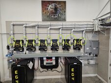
18 month DIY project finally done: 39kW inverter power off grid system

Yes, the equipment cooling keeps the units nice cool and so it keeps them quiet, also. I'm sure the lifespan of the inverters will be better also when they usually running cool. I'm very happy with the cooling/loudness results with the small 9,000BTU ducted mini split which does not cost much energy.
I have 4 voltronic max axpert 8kw side by side and i am thinking about something similar, but jointed all the way so i can remove all the small filters and put a main big filter to simplify this part of the maintenance.

In the voltronic these filters are not too good, they dont fit well and they clog quick, and each one has 4 M3 small screws that are a pain in the butt.
I have to take them apart and blow them with compressed air often and it takes too much time. At least i will 3d print a filter that i can press fit on the side or take out with a simple lever or bracket instead of those pesky screws. Do you think this would be a good idea?
 
I have 4 voltronic max axpert 8kw side by side and i am thinking about something similar, but jointed all the way so i can remove all the small filters and put a main big filter to simplify this part of the maintenance.
That's a great idea to ease maintenance!
In the voltronic these filters are not too good, they dont fit well and they clog quick, and each one has 4 M3 small screws that are a pain in the butt.
I have to take them apart and blow them with compressed air often and it takes too much time.
Yes, the small screws are a pain. The EG4-6500EX only have one screw per filter grille, but it's still a pain. So I followed the advice in this video and replaced the screws with a small flat magnet and it works great. Now the filter removal/re-installation is done in seconds.

I don't have long term experience with the quality of the filters so far (my system is running since 20 days). I thought I will check them every 30 days and depending how they will look like I may decide to change them to different filter types... we will see.
At least i will 3d print a filter that i can press fit on the side or take out with a simple lever or bracket instead of those pesky screws. Do you think this would be a good idea?
Sounds like a doable idea for your situation. I will stick with the individual filters with the magnet hack.
 
Yes, the small screws are a pain. The EG4-6500EX only have one screw per filter grille, but it's still a pain. So I followed the advice in this video and replaced the screws with a small flat magnet and it works great. Now the filter removal/re-installation is done in seconds.
I thought about fixing some filter with a magnet but i was scared of disturbing something in the electronics of the inverter with the magnet
 
FI've done a bit math of the today's power parabola and found the following formula for the PV power:

f(x)≈−0.386082x^2+9.6551x−46.0318

Where x is the current time in 24h system. The diagrams zero crossings are at about 6.25 (which is 6:15 in the morning) and 19.25 (which is 19:15 in the evening). The max. will be at 12:30 with a power of 14.33kW.
If I take the integral from 6:15 to 19:15 I will get a potentially daily energy production of 115.3kWh.

If I take the panels spec I would calculate a max. NMOT power of 13.6kW and a max. SCT power of 19.4kW. So my values are between these two, which sounds realistic for me.

View attachment 212369
It's nice to see that the forecast calculations I made about 2.5 weeks ago are almost exactly the same as today's result. Yesterday was the first cloudy day since the system went into operation and because of this the batteries could only be re-charged to around 79% SOC by end of the day. During the night, the battery charge level dropped to 23% before the new solar production began. So today is the first day where all the possible PV energy was really consumed to recharge the batteries to 100% again and driving the loads of the house in parallel. With this data I was able to compare the today's results with the forecast for the first time.

Here is the today's diagram (these many load peaks [blue line] is the load of the 5 ton central heat pump):

1715909847536.png


Today's max. power was 14.3kW at 12:48pm (projected 14.33kW at 12:30pm) and the whole PV energy production was 117kWh (projected 115.3kWh).

It looks like the above formula describes my system very well (at least in this season with comparable ambient temperatures - today we had a max. of 104°F [40°C] ). By end of June, beginning of July we usually see some days with >=122°F [>=50°C]) and I'm sure, I will loose some power and energy with these extreme high temperatures (PV panel TC-Pmax is -0.36%/°C) - very curious about it!
 
Not 100% related to solar, but interesting to see the power factor diagram related to the load over a typical day (it influences at least the required power capabilities of the inverters - e.g. a power factor of 0.5 requires the double amount of current from the inverter to fulfill the required real power).

Power factor diagram:
1716045076094.png

Power usage diagram:
1716045184452.png


When the load is low, the power factor is low (bad). The reason for that is, that all the small consumers (all sort of electronic devices like computers, mobile chargers, WiFi router, etc.) usually have a low power factor. As soon as larger loads kickin' in (e.g. HVAC compressor, pool pump etc.) the power factor jumps and stay while running at upper values direction to 1. At 8.45am my pool pump starts and the power factor jumps from about 0.65 to 0.95 and staying like this until 5:45pm when it stops. From this time on, the power factor gets lower and lower over the whole night because only small electronic loads are active until the pool pump starts again at 8:45am in the next morning.

I guess the short spike drops from 0.95 to 0.8 over the day are produced by the startup surge of the central HVAC (even with SoftStart it's a high inductive load which lowers the power factor for a short time).

Only when the central HVAC is running in the night, the power factor jumps in direction 1 because it's overall load is much higher than the small electronic loads and while the HVAC is running, it's power factor is better compared to the electronic device power factors.
 
Last edited:
Just an update about insurance.

Today I've informed my property insurance company (by phone) about the installation of the solar system.

The only one question the agent asked was, "how many panels are installed on the roof?". I told him 40 and he told me the re-building costs of the house will be increased by $110,000 and because of that, the annual premium will rise by 30%. I have no idea how they calculate the increased re-building cost.

In my next life I may think about being a founder of an insurance company... ;)
 
Last edited:
Today, I've got my first energy bill since solar system is in use.

$20.50 (Basic service charge plus some fees and tax)

(Btw. This includes 12kWh for the couple of hours from midnight to 11am on 04/26, before I've flipped the transfer switch to the solar system. By coincident, my electrical meter reading was on the same day when the final inspection was passed and the system went into production).

With my usage of 2,046kWh in this time range, the bill would have been around $345 without solar.
As a result, my first monthly solar savings are $325.

Some findings over the last 30 days:
  • no issues! So far, the system runs like a Swiss watch
  • zero kWh grid usage since system is in use
  • highest peak house load was 18.5kW
  • highest peak solar power was 19.8kW
  • highest peak solar daily production was 120kWh
  • highest peak battery discharge power was 14kW
  • overall system efficiency over the last 30 days was 74% (2,770KW PV produced, 2,046kWh consumed)
  • yesterday was the hottest day so far with about 104°F and with the highest usage of 120kWh
  • lowest battery SOC before new solar production starts was 32% (this morning)
  • the batteries were able to be recharged to 100% on 29 out of 30 days (just one very cloudy day)
  • the charge/discharge power of all 12 batteries is still very nice distributed (no drift), very low cell delta
  • active equipment cooling works flawless
Now, I can foresee that the installed PV power will not be enough to be always able to drive the house 100% off-grid on all sunny AND extremely hot days here. Yesterday I've consumed a max. of 97kWh and the PV production was 120kWh to cover the load and re-charge the batteries. The PV production diagram from yesterday shows that my solar production of 120kWh was nearly maxed out (maybe 122kWh would have been possible).
1717079927624.png

But we will see even higher temperatures (110-120°F) over the next couple of weeks and because there is no more PV production possible, I'm sure I will need grid support (at least some kWh) in the coming days/weeks. With higher temperatures the production will decrease, also.

Looking forward how my smart home rules to activate AC-in contactors will work...

It looks like my sweet spot would be about to add 4-5kWp 8-10kWp more PV modules to completely cover my max. usage (on usual sunny days). We have not changed our usage behavior because of the solar system - so there is potential room for reducing the load with some convenience losses while arranging the energy usage to be more off-grid friendly...
It seems that the battery capacity of 60kWh will be enough to cover everything. I'll find out.

Maybe I will add some panels next winter... not sure about it (I still have 4 MPPT's left and some space on the roof).

Here are some more diagrams over the last 30 days:
1717082077267.png

1717082101084.png

1717082138674.png

1717082161122.png

1717082176335.png

1717082224317.png

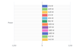
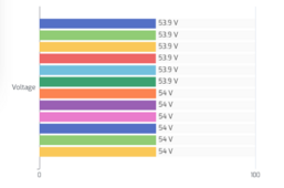
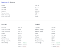
The load over the batteries is well distributed (here is a snapshot while charging with 5100W):
1717082329297.png 1717082352253.png
 
Last edited:
After I have the first complete month (May) completely off-grid running, I've try to take a deeper look into my battery data and would like to share them.

1717344236338.png

I think I can calculate the cycle count by using the kWh charged/discharged (the average of both is 1007.5kWh) and divide it by my total battery capacity of 60kWh which will result in 16.8 cycles for the 31 days in May. So I can assume 0.55 cycles per day in my case. The battery spec says 7,000 cycles are possible with a DOD of 80% (in my case it's usually between 50%-80%) - that's a calculated theoretical lifetime of >35 years... (which is a bit nonsense for sure because they will age out much earlier, but it gives me a good feeling that the cycle time will not be a problem for my system. Also it may be a bit less, because my ambient temperature for the batteries are between 27-30°C which is not the optimum specified 25°C to reach the full cycle time (but still very good).

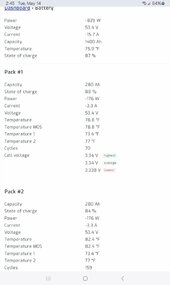
Unfortunately, SolarAssistant does not provide many battery details, even though the batteries are individually connected to SA via RS485.
E.g. it does not report the cell voltage for each cell, just the maximum, minimum and average per battery. Also the balance status is not indicated (and no details about cycle count, the 6 temperature sensors per battery, etc.).
The EG4-LL battery MODBUS protocol provides all these data, but SA just don't display all of them.

So I try to find out a bit more about the internal battery/cell status based on the minimum and maximum of each battery and created diagrams and now I ask myself if these data make sense, are the data consistent, are the batteries healthy, etc. for my feeling it looks ok and the load is distributed more or less evenly over all batteries?!

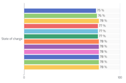
The diagrams show the SOC and cell voltages for one typical day. The batteries reached 100% SOC and stopped charging at about noon and stays constant at 100% until around 3pm with only very little small usage. Between 3pm to 5pm the battery were charged/discharged a bit more, but still only for small amounts and stays around 99%-100% SOC. From 5pm the SOC starts to decrease.

SOC:
1717343217758.png

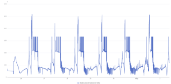
Battery current reported by the 6 AIO's:
1717343429617.png

Battery current reported by the 12 batteries (over the whole day):
1717343798153.png

Battery current reported by the 12 batteries (zoomed in a little further to the time when 100% SOC was reached):
1717344032820.png

Highest Cell Voltages:
1717342677354.png

Lowest Cell Voltages:
1717342968136.png
 
Last edited:
After 41 days in a row completely running off-grid (without any grid support, not even connected the AC-in to the grid), it happened last night.

We see a huge heat dome here in the southwest (about 3-4 weeks earlier than usual) and our central AC is now running for >60% of the time. Official temperature yesterday was 110°F here in town but around our house it was 115°F. Today it will be even hotter (I think around 118°F-120°F).

This was the first real life test to see how the smart home rules to control the grid support will work. The boundary conditions are as follows:
  • AC-in's are always disconnected from the grid via remote controlled contactors.
  • AIO are running always in SBU mode.
  • The "back-to-grid" voltage (program 12) is initially set to 49V (like disabled).
  • The "back-to-battery" voltage (program 13) is initially set to 55V (like disabled).
  • By intention, no closed loop communication, so the programs 12 and 13 are based on voltages!
  • Even without using closed loop communication, I've got the SOC values directly from the batteries which are connected to SolarAssistant.

The rules are designed like this (via OpenHAB automation rules communicating via MQTT with SolarAssistant):
  • If the SOC will reach 7% one smart home rule closes the AC-in contactors (now the AIO inverters will shift it's phase angle to be synchronized with the grid, but the grid is still not used and the off-grid inverter inside the AIO is still powering the house exclusively)
  • If the SOC will reach 6% the rule changes the "back-to-grid" (program 12) value to 52V (which is way higher than the current battery voltage at 6% SOC). This suddenly forces the AIO's to activate it's bypass relays and the complete load is driven by the grid. In parallel, the batteries are charged from the grid at the amperage which is chosen by program 11 (max. utility charging current).
  • If the SOC will reach 50% the rule will set the "back-to-battery" (program 13) to 52V (which is way lower than the current battery voltage at 50% SOC). This suddenly forces the AIO to switch back to the "solar/battery" mode and the bypass relays will switch back to open.
  • A different smart home rule is triggered when the AIO mode changed from "grid" to "solar/battery" and adjusts the values for program 12 and program 13 to it's initial values (49V and 55V). After that, the rule disconnects the AIO's AC-in's by opening the contactors.
This rules are always active to manage the grid usage only if required (the grid is disconnected for the most time to save this idle grid usage of about 50W per AIO if their AC-in's are just connected to the grid - even if grid not used).

Some findings (some of them I was not aware before):
  • If no PV production (it happenes at night ;) ), the grid is driving the load AND charging the batteries with the given amperage in setting 11 - this is as expected (the minimum grid charging amperage for setting 11 is 2A).
  • As soon as PV production starts in the morning, the grid does NOT longer charge the batteries but just drive the house load - I like this a lot, because I want to minimize the charging of the batteries from the grid - I have not expected this behavior. Update: It's because the program 16 (Charger source priority) is set to CSO!

The following diagrams showing the situation. At 1:12am the 7% SOC were reached, the AC-in contactors were closed because of that and the grid voltage jumped from 0V to 120V. At 1:20am the 6% SOC were reached and the AIO's changed to "Grid" mode (bypass) and drove the house load. In parallel the batteries are grid charged with about 3kW (I've used 10A max. grid charging for testing per AIO). At around 5:35am PV production started and suddenly the grid based battery charging stopped and only PV is charging the batteries from now on (without any mode change or other interactions). PV does not support the load in parallel, just charging the batteries. The SOC of 50% were reached at around 10am and the AIO's were switched back from "Grid" to "Solar/Battery".

1717693645602.png

1717694026579.png

1717693673102.png

1717693700962.png


Overall, the rules are working as expected and I haven't noticed any dropout during the mode switches of the AIO's (program 03 is set to "Appliance mode" APL).
 
Last edited:
After 41 days in a row completely running off-grid (without any grid support, not even connected the AC-in to the grid), it happened last night.

We see a huge heat dome here in the southwest (about 3-4 weeks earlier than usual) and our central AC is now running for >60% of the time. Official temperature yesterday was 110°F here in town but around our house it was 115°F. Today it will be even hotter (I think around 118°F-120°F).

This was the first real life test to see how the smart home rules to control the grid support will work. The boundary conditions are as follows:
  • AC-in's are always disconnected from the grid via remote controlled contactors.
  • AIO are running always in SBU mode.
  • The "back-to-grid" voltage (program 12) is initially set to 49V (like disabled).
  • The "back-to-battery" voltage (program 13) is initially set to 55V (like disabled).
  • By intention, no closed loop communication, so the programs 12 and 13 are based on voltages!
  • Even without using closed loop communication, I've got the SOC values directly from the batteries which are connected to SolarAssistant.

The rules are designed like this (via OpenHAB automation rules communicating via MQTT with SolarAssistant):
  • If the SOC will reach 7% one smart home rule closes the AC-in contactors (now the AIO inverters will shift it's phase angle to be synchronized with the grid, but the grid is still not used and the off-grid inverter inside the AIO is still powering the house exclusively)
  • If the SOC will reach 6% the rule changes the "back-to-grid" (program 12) value to 52V (which is way higher than the current battery voltage at 6% SOC). This suddenly forces the AIO's to activate it's bypass relays and the complete load is driven by the grid. In parallel, the batteries are charged from the grid at the amperage which is chosen by program 11 (max. utility charging current).
  • If the SOC will reach 50% the rule will set the "back-to-battery" (program 13) to 51V (which is way lower than the current battery voltage at 50% SOC). This suddenly forces the AIO to switch back to the "solar/battery" mode and the bypass relays will switch back to open.
  • A different smart home rule is triggered when the AIO mode changed from "grid" to "solar/battery" and adjusts the values for program 12 and program 13 to it's initial values (49V and 55V). After that, the rule disconnects the AIO's AC-in's by opening the contactors.
This rules are always active to manage the grid usage only if required (the grid is disconnected for the most time to save this idle grid usage of about 50W per AIO if their AC-in's are just connected to the grid - even if grid not used).

...
With the recent stories of inadvertent export leading to problems for Off grid with grid as backup setups I like your automatic external relays that disable "AC in".
 
With the recent stories of inadvertent export leading to problems for Off grid with grid as backup setups I like your automatic external relays that disable "AC in".
I think the AC-in contactors together with using only the SBU mode, there should be a very low risk to run into this problem.

On top of that, I only let the AC-in contactors close if the house has a minimum load of >1000W (if the load is lower, the smart home rule activates some additional loads for a short time to get over the 1000W and turn them off again after the contactors are closed). This also prevents possible grid backfeed problems (error 60 - Power feedback protection) which I've seen while having no load while doing initial tests a couple of month ago.
 
Thanks.

Is this still the case when it fails over from battery to utility? If yes, is it because there's a big empty battery to absorb any "backfeed potential."
The Inverter only runs in parallel with the AC input in SUB mode.
Every other mode is separate like most off grid AIO's.
 

Hmm...

Just connected in parallel. Just like a grid-tied inverter, Set to zero export.

This part of your answer says to me that your first part should be "kinda, but with a different set of rules". That's basically what Victron PowerAssist is... the inverter syncs to the incoming AC (like grid-tie) and boosts it if the incoming AC isn't adequate for the loads. So when PowerAssist is active and the load is being split between the AC input and inverter, it's similar to SUB mode when both inverter and grid are powering the loads.

If a SUB inverter were powering a small circuit on my home (200W), and my home regularly consumes over 400W, the likelihood of backfeeding is very very low.
 
Just an update about insurance.

Today I've informed my property insurance company (by phone) about the installation of the solar system.

The only one question the agent asked was, "how many panels are installed on the roof?". I told him 40 and he told me the re-building costs of the house will be increased by $110,000 and because of that, the annual premium will rise by 30%. I have no idea how they calculate the increased re-building cost.

In my next life I may think about being a founder of an insurance company... ;)
Hmm I wonder what the increase would be for say 20 panels (potentially a case for the Jumbo 650+W panels)
 
Hmm...


This part of your answer says to me that your first part should be "kinda, but with a different set of rules". That's basically what Victron PowerAssist is... the inverter syncs to the incoming AC (like grid-tie) and boosts it if the incoming AC isn't adequate for the loads. So when PowerAssist is active and the load is being split between the AC input and inverter, it's similar to SUB mode when both inverter and grid are powering the loads.

If a SUB inverter were powering a small circuit on my home (200W), and my home regularly consumes over 400W, the likelihood of backfeeding is very very low.
There is a difference.
Victron grid assist. Uses the grid up to the set limit. And the battery fills in the gap. Perfect for shore power limitations.

SUB mode is exactly like a grid-tied inverter. PV does what it can and grid does the rest.
 
It's set to never export. But like everything set to zero export, nothing is perfect.

Okay.

"Like PowerAssist" is clearly a no.

Zero feedback notwithstanding, I think the fundamental answer to my not-so-clearly-stated query is that they both act in a synchronous way, i.e., two simultaneous sources powering loads analogous to a grid-tie inverter but with a different set of operational rules.

I'm actually impressed. It read that way to me in the manual, but that invoked Power-Assist like behavior, and I refused to believe it. I pictured it as powering loads with PV and then use grid for PowerAssist-like function, where it would turn on and off as needed, and I didn't see how that could work.

Your description makes total sense, and I should have figured that out as that's really the only reasonable way it could work. Thanks!
 
I still try to understand this with @timselectric explanation and with given schematic (posted by @RCinFLA) of typical AIO designs and I wonder how this may work.

SBU with bypass active:
I assume, the "AC input Pass-Through Relay" is closed and the H-Bridge "Stage 2 Sinewave PWM Converter" is not used (inactive - all IGBT's open) at this time which means the inverter part of the AIO is not running - not inverting. All other parts (left side of the HV DC Bus) are still active to charge the Batteries from PV. BUT as long as no PV is available (see my diagrams from the previous post), the grid is also charging the batteries?! So the "Stage 2" H-Bridge must be active in a way to charge the batteries, but not putting power out as an inverter.

SUB, as far as I understand it:
I assume, the "AC input Pass-Through Relay" is closed and both the inverter H-Bridge "Stage 2" is providing power (inverting) using PV energy and in parallel the grid provides the part which PV is not able to deliver to fulfill the load requirements.

But for me it looks nearly the same. So is it just a matter of how the "Stage 2" H-Bridge is controlled (software) if it's used to just charge the batteries from the grid in SBU bypass mode (if solar is not available) and on the other side in SUB mode the H-Bridge is controlled in a way to invert the PV power to provide power to the loads (together with help from the grid if required)?

I can not really see why this schematic would it make impossible to feed energy back to the grid in case of SBU mode but it should be possible in SUB mode? Or is this given schematic just not the right one to describe the SBU and SUB modes of these type of inverters?

I'm a bit lost...


1717722911378.png
 
This is as simple as I can make it.
The inverter and AC charging share components.
And power can only flow in one direction. It's either an inverter or a charger. (Never both at the same time)
In SBU mode it's a charger in bypass.
In SUB mode it's an inverter, powered only from solar. (Battery is disconnected)

Edit to clarify:
The battery output is disconnected (FETs I assume).
But input (charging) still connected.
 
Last edited:
This is as simple as I can make it.
The inverter and AC charging share components.
And power can only flow in one direction. It's either an inverter or a charger. (Never both at the same time)
In SBU mode it's a charger in bypass.
In SUB mode it's an inverter, powered only from solar. (Battery is disconnected)

Edit to clarify:
The battery output is disconnected (FETs I assume).
But input (charging) still connected.
Ok, I can follow your explanations. So it's just a matter of PWM timing and controlling of the FET (or IGBT) gates of the H-Bridge if it's running as an inverter (power flow direction to AC-out) or as a charger in bypass (power flow direction from AC-in) where AC-in is identical to AC-out in case the bypass relay is closed.

Trying to sum it up in my own words:
Because it's the same circuit, a software bug or glitch in the H-Bridge controlling algorithms could theoretically result in a grid backfeed even in SBU mode - but in usual situations where the AIO is working as designed, this should/could never happen. But in SUB mode, the H-Bridge controlling software is designed that the H-Bridge is used always in inverter mode and always running in parallel to the AC-in/AC-out (grid) which makes it much more likely to accidentally have a grid backfeed event.
 

diy solar

diy solar
Back
Top