diy solar

diy solar

ATS Grounding question

JASHOTZE

New Member
Joined
Jan 22, 2021
Messages
43
I’m installing a MOES ATS (same one as Will always uses). It has L/N for the two power inputs and output which handles neutral bonding. I’m not sure how to handle the grounds.

Shore power ground to the ground bar on DC distribution panel. But then the output from ATS power would have a ground from nowhere to DC distribution panel?

If I had one ground from DC panel to both wires via a bar, I would be grounding the output wire down the length of shore power cord that’s not in use during inverter use.

Trying to not get a weird ground loop here. Can output from ATS just be L/N?

This is a 12 volt system with Renogy 2000 watt inverter and 30 amp shore power to a travel trailer. Thanks!
 
Your inverter handles the required neutral/ground bond. If you are installing a transfer switch i would suggest a listed device.....
 
Your inverter handles the required neutral/ground bond. If you are installing a transfer switch i would suggest a listed device.....
The manual states the inverter does not handle neutral ground bond.
 
Your inverter handles the required neutral/ground bond. If you are installing a transfer switch i would suggest a listed device.....
Actually that’s the exact one I have. I either read mine wrong or am just dumb.

So I still need to know how to handle the two grounds from shore power and output from ATS.

Shore power ground to common grounding bar makes sense. But the output line I can’t figure out.
 
I just re-watched wills video on it and he just wired all the grounds together. But when an output is to an AC Distribution panel, that will create a ground loop because at the end of the output line, it’s grounded as well.
 
You can ground a wire that is not in use at one end without creating a "ground loop". All the grounds should be connected to each other in the ATS. When on inverter the neutral is disconnected from the shore cord, and when on shore the neutral is disconnected from the inverter. The approved ATS are designed to switch both neutral and hot
If this is in a RV you need to make sure your converter is not trying to charge the batteries the inverter is using....turn it off somehow
 
Grounds from both TS power sources should be bonded and connected to the main distribution panel ground bus.
 
I have the converter wired out of the ATS directly at shore power to prevent inverter loop.

I sort of came to the same conclusion that wiring the shore power and output ground together would be the best. Thanks for the help!
 
Did you put a new breaker in the ATS, If so how did it work out?
 
No I just put the hot wire to the converter into the same port of the ATS with shore power. I put a 15 breaker on the line since it was skipping the breaker on the AC distribution panel. This way regardless of what the ATS is doing, if shore power is present it’s charging the battery.
 
just wired all the grounds together. But when an output is to an AC Distribution panel, that will create a ground loop because at the end of the output line, it’s grounded as well.
@FilterGuy - since you’re well grounded, ahem:

(Maybe this is in a thread somewhere? I search-featured and didn’t see it)

I don’t have one of these ‘moes’ automatic transfer switches so I can’t test it. Do you know how the moes ats handles the nuetral/bare earth? In other words- thinking about the recent tingly meg RV thread- would using the moes ATS energize the bare/green/earth/chassis in an RV because of the neutral/earth tie in the RV?

Is this a concern?
 
Last edited:
The ATS does not have any input or output for Earth ground and does no switching of the neutral or earth, since the earth ground is not included. I think the correct answer is tie the shore power earth ground and output wire earth ground together. Small ground loop but its either that or not grounded at all.
 
shore power earth ground and output wire earth ground together.
It’s the neutral and earth/bare tie in the RV that’s in question.
When plugged to shorepower the plug-in post should have the tie and not the RV; when not on shorepower the RV should be tied.
 
The ATS does not have any input or output for Earth ground and does no switching of the neutral or earth, since the earth ground is not included. I think the correct answer is tie the shore power earth ground and output wire earth ground together. Small ground loop but its either that or not grounded at all.
In an RV the Hot and Neutrals are switched. Grounds remain bonded.

Any Neutral-Ground bond will be at the power source. Utility power back at the main panel, On-board generator at the generator, inverter at the inverter. As the power from these sources are kept separate there will be only one neutral-ground bond and no loops.
 
@FilterGuy - since you’re well grounded, ahem:

(Maybe this is in a thread somewhere? I search-featured and didn’t see it)

I don’t have one of these ‘moes’ automatic transfer switches so I can’t test it. Do you know how the moes ats handles the nuetral/bare earth? In other words- thinking about the recent tingly meg RV thread- would using the moes ATS energize the bare/green/earth/chassis in an RV because of the neutral/earth tie in the RV?

Is this a concern?
Is there a diagram of the system? I'll need that to help.
 
I don’t have one of these ‘moes’ automatic transfer switches so I can’t test it
So there isn’t a diagram. BUT time2roll said,
Any Neutral-Ground bond will be at the power source. Utility power back at the main panel, On-board generator at the generator, inverter at the inverter. As the power from these sources are kept separate there will be only one neutral-ground bond and no loops.
seems like such an obvious thing: the inverter gets connected to the ATS as does ‘grid’ power; both L snd N get switched one to the other. But the earth that grounds to the frame isn’t switched and if the grid bare is joined to the RV bare (and subsequently the chassis) then you have that potential circuit to the chassis situation, no?
 
Let's separate the discussion. 1) How to string the ground wire between components

I will address the ground wire between components in this post.

Grounding.

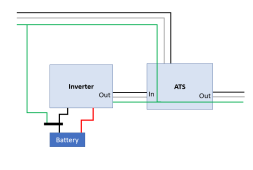
If I am reading the OP correctly, the system has an inverter, ATS, and grounded DC negative. The way I would do this is shown below.

1636064760686.png
Inverters do not tie negative to ground internally, so there is no ground loop in the above diagram.

Inverter-chargers:

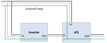
Some people like to install ATSs with inverter chargers so they can cut the inverter charger out of the loop for maintenance. Far too often, when an ATS is installed with an inverter charger, ground loops are unnecessarily created. In almost all cases the ATS and the Inverters will tie all ground inputs and outputs together. People dutifully connect everything together and end up with this:

1636063877475.png

In this case, the ground connection between the inverter output and the ATS is not needed. The following is properly grounded and does not have the ground loop.

1636063906594.png
 
I don't think that ATS just above is needed. Or the ATS IN would be connected to the generator. That inverter has an internal switch.
 
Back
Top