diy solar

diy solar

Pre-Charge Switch

chrisski

Solar Boondocker
Joined
Aug 14, 2020
Messages
5,326
Really want to know if my wiring diagram at the bottom will work.

This is in REference to @FilterGuy ’s Inverter DIsconnect with pre-charge in the resources at:
I m getting reday to build the 24 volt version:
C1D94F85-C9C8-4400-BF01-1DAAEB6BC12A.jpeg
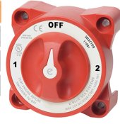
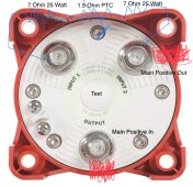
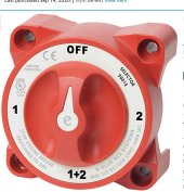
Instead of Using the linked Perko switch 9BDD3856-A7CF-4F52-B0B1-CD524C97EDFC.jpegI want to use a similar Blue Sea2356B1FD-9BBE-4322-9C9F-1B7F5E3B899F.jpeg

I think it will be the same thing, but the difference is the Blue Sea does not have the all and would be briefly shut off the circuit when I go from position 2 to position 1. I think the Perko switch keeps the circuit live the whole time.

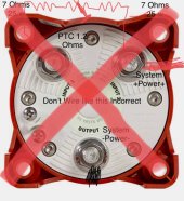
This is my plan to wire the Blue Sea switch like this:

So with this, this also will pre-charge the whole system which is not just the inverter but a converter that likes to spark when first attached to the DC side and a 24 volt DC to DC converter that likes to spark on the DC side also. I also have the input and output reversed as per the labeling, but with a DC switch should not matter (reversing polarity on a polarized DC circuit breaker could result in fire).
0A81319E-CB4F-49FC-B676-5945B2FEB8E4.jpeg
EDIT Correct Switch
976CBA7E-0D32-49CB-B8B3-4FCED9BDA7AA.jpeg
 
Last edited:
Why would you be wiring the switch with both the battery positive and negative? The inverter's positive goes to the switch's output, not the battery negative.

One big problem with that switch. It requires you to remember to switch to position 1 for a few seconds then to switch to position 2, then you turn on the inverter, etc. Nothing prevents you from simply turning straight from Off to position 2 which will completely bypass any attempt to precharge.
 
Really want to know if my wiring diagram at the bottom will work.

This is in REference to @FilterGuy ’s Inverter DIsconnect with pre-charge in the resources at:
I m getting reday to build the 24 volt version:
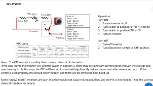
View attachment 83142
Instead of Using the linked Perko switch View attachment 83143I want to use a similar Blue SeaView attachment 83144
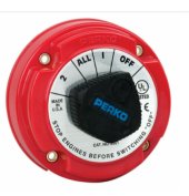
I think it will be the same thing, but the difference is the Blue Sea does not have the all and would be briefly shut off the circuit when I go from position 2 to position 1. I think the Perko switch keeps the circuit live the whole time.

This is my plan to wire the Blue Sea switch like this:
View attachment 83146
So with this, this also will pre-charge the whole system which is not just the inverter but a converter that likes to spark when first attached to the DC side and a 24 volt DC to DC converter that likes to spark on the DC side also. I also have the input and output reversed as per the labeling, but with a DC switch should not matter (reversing polarity on a polarized DC circuit breaker could result in fire).
That switch will work but after pre-charging, don't delay in the off position while going to full on.
 
One big problem with that switch. It requires you to remember to switch to position 1 for a few seconds then to switch to position 2, then you turn on the inverter, etc. Nothing prevents you from simply turning straight from Off to position 2 which will completely bypass any attempt to precharge.
That is an excellent point.
 
Let me reiterate - if you wire as shown in your diagram then when you switch to position 2 (precharged or not) you are creating a dead short between the system positive and negative. Don't do that. Bad things will happen.
 
Why would you be wiring the switch with both the battery positive and negative? The inverter's positive goes to the switch's output, not the battery negative.
I agree with this statement. The diagram is showing the Negative/Black System minus and the Positive/Red system plus. I certainly hope he doesn't try to wire the switch that way, or he will be shorting the system.
 
Let me reiterate - if you wire as shown in your diagram then when you switch to position 2 (precharged or not) you are creating a dead short between the system positive and negative. Don't do that. Bad things will happen.
I agree with this statement. The diagram is showing the Negative/Black System minus and the Positive/Red system plus. I certainly hope he doesn't try to wire the switch that way, or he will be shorting the system.
Well I need to redo that diagram to say system + in and system + out. The diagram is not what I pictured in my mind.
 
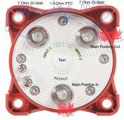
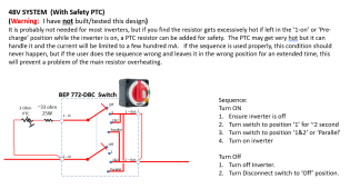
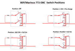
BTW: The perko switch in the resource is not rated for 48V. (I did not realize that originally). I found another switch that will provide the same function but requires different wiring. I have one on order to test but it is not due to arrive till March. I will update the resource when the testing in done.

Meanwhile here is the new 48V design:

https://www.satpro.tv/bepproinstaller400adualbankcontrolswitch-mc10.aspx
1644444434312.png
1644444512799.png
 
Diagram and original post updated to:
1EB0B52D-06DD-4022-AE7F-73B3DE703FD6.jpeg
Now that you @rmaddy and @FilterGuy have mentioned the benefit of the foolproof (and hopefully chrisski proof) way that the Perko is built, I plan on ordering a Perko Switch for this project. I sometimes have to remind myself I build these not just for me, but for the others in my family and whoever ends up with this many years from now.
99BA9A82-111C-4CF7-BD00-6CA22B35AED4.jpeg
Can you confirm the Perko is a contact before break switch? At least I think that’s the term for not shutting off even momentarily when going from 1 —> all —> 2. Switch could be built either way.

Blue Sea has one similar that is break before contact, but will ask let you turn on backwards and bypass the resistors.
396C7C0C-F9DF-48AB-A5D7-6594756CA9D4.jpeg
 
Last edited:
I sometimes have to remind myself I build these not just for me, but for the others in my family and whoever ends up with this many years from now.
Yup!!! That is why I do the big ugly perko instead of a pushbutton. Many of the systems I build are for others, and none of them wear pocket protectors!!! :) Even if the system would only ever be used by me, I know that I am not immune to doing stupid.... Consequently, keeping the user interface as simple as possible is important.
 
Are any of the switches being discussed "approved for use under load"?
I know the Blue Sea Ones are not. There is supposed to be no loads when these switches are turned on or off. Only to pre-charge the capacitors. Not to break the circuit when the 3000 watt inverter is in full use.

I did not see a UL rating on the other switch, so I assume not.
 
Are any of the switches being discussed "approved for use under load"?
I don't see a switching spec in the literature, but many (Most) high-amp switches have a much smaller switching rating than the current-carrying rating. Even if they were rated to be switched at the full rating, that is not something you would want to do unless it was an emergency.
 
I know the Blue Sea Ones are not. There is supposed to be no loads when these switches are turned on or off. Only to pre-charge the capacitors. Not to break the circuit when the 3000 watt inverter is in full use.

I did not see a UL rating on the other switch, so I assume not.
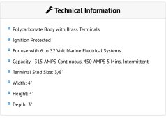
BTW: The perko is rated at 250A and the Marinco is rated at 400A. Presumably, the Marinco would be able switch higher currents as well.
 
This Perko 8511DP is UL listed and has a continuous rating of 350 and an intermittent rating of 450 amps for 5 minutes. I think I will get that one.


The saw switch is linked in the Resource, but does not have the UL sticker on it. There is a certificate listed on the first link. The one thing I’m not used to is the brass terminals.

E60B670D-5653-45AE-968F-C57D0D37B16C.jpeg
 
That’s what I built, works great. Just one 100w (integrated heat sink )15ohm? resistor on position one wired to position 2. In position one it loads up the inverter over about 8 seconds, law of diminishing returns, it’s most the way there in 3 seconds and slowly finishes off. it’s a no brainer click, click, click amd it’s all on. Can’t get hot. The voltage drops and inverter shuts down with that much resistance. all position is just both and it won’t draw through resistance when a solid connection exists. Works every time, no sparks, no heat, no problem.

if someone forgets, doesn’t read the sign that says wait 5 seconds at positin one, the 1 second it was there is enough to bring the voltage to 12 or 15 on a 24v system and the resulting inrush is still no problem as the potential is less. I tested it.

the switch itself does get a little bit of heat under a few hundred amp loads, but the option then is hardwired…. I like the switch.
 
I don't see a switching spec in the literature, but many (Most) high-amp switches have a much smaller switching rating than the current-carrying rating. Even if they were rated to be switched at the full rating, that is not something you would want to do unless it was an emergency.
I searched far and wide for one of those switches that is "approved for use under "ANY" load" and could not find ONE.
I know folks do use them under load and some post pics of melted and broken switches because they did not RTFM.

I have found 2 alternatives which are approved for use under load.

1) an Anderson SB120 connector: Hot Plug Current Rating Amperes - 250 cycles at 120V DC 60A
The Anderson plug is hard to find these days. There tons of chinese knock offs flooding the market.

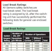
2) Siemens Safety Switch: 6,000 operations with current
The Siemens is much bigger than the typical red box switch but it is also fusible, UL Listed and a child with a broom can't break it.
Class-T fuses can be used in some 100 Amp and larger switches.
Siemens Load Break.JPG
 
Would a 1.2 ohm 4.34 PTC rated for a 12/24 VDC system work in place of the now discontinued 1.2 ohm 5 amp linked in the resource?

This is a soon to be in stock PTC 1.2 ohm4.34amp thermistor. The resource listed a 5 amp one, but that part was discontinued.
Specs:
======================
The 7ohm 25 watt resistor and the 1.2 ohm 5 amp PTC is not availabel from the linked site in the resource:

I want to try this in stock 25 watt 7 ohm resistor from mouser:
I think I've said before here that I don't see the PTC as ever being required. It serves to increase the resistance over time to prevent the resistor from burning out, but the fact is that the whole pre-charge even is going to be one second or less. Not enough time for a PTC to warm up and slow down the current. Just worry about the resistor.
 
Back
Top