The author of the youtube issue metered NO N/G bond with the LV6548s drawing on batteries, with 0.2A on Ground Conductor. In Utility bypass, he metered a short between N/G at the inverters and 5+ A on the ground conductor. Victron inverters do this also, if one forgets to program their onboard N/G bonding relays.


You are using an out of date browser. It may not display this or other websites correctly.
You should upgrade or use an alternative browser.
You should upgrade or use an alternative browser.
MPP LV6548 Ground/Neutral Safety?
- Thread starter Tetawon
- Start date
Thanks for testing, truly appreciate your time!
Lt.Dan
Solar Wizard
To be honest I have no idea what I'm doing. Lol. Do these results confirm the inverter acts like MPP says it should?
Were you testing in bypass or battery (inverting) mode? Can you post a wiring diagram of your system?To be honest I have no idea what I'm doing. Lol. Do these results confirm the inverter acts like MPP says it should?
Lt, Dan,To be honest I have no idea what I'm doing. Lol. Do these results confirm the inverter acts like MPP says it should?
If your 6548s are bypassing the Utility, and your measurements are between the subpanel and the inverters....that's perfect! I'm extremely limited with "residential" electric (BY CHOICE). I spent 25 years working internationally on offshore Oil Platforms and Vessels before retiring.
timselectric
If I can do it, you can do it.
- Joined
- Feb 5, 2022
- Messages
- 18,807
Excellent
timselectric
If I can do it, you can do it.
- Joined
- Feb 5, 2022
- Messages
- 18,807
The video shows testing in the wrong place.The author of the youtube issue metered NO N/G bond with the LV6548s drawing on batteries, with 0.2A on Ground Conductor. In Utility bypass, he metered a short between N/G at the inverters and 5+ A on the ground conductor. Victron inverters do this also, if one forgets to program their onboard N/G bonding relays.
That location would only show a problem at that panel or on down the line.
Lt.Dan
Solar Wizard
In bypass mode right now. I don't have a wiring diagram unfortunatelyWere you testing in bypass or battery (inverting) mode? Can you post a wiring diagram of your system?
timselectric
If I can do it, you can do it.
- Joined
- Feb 5, 2022
- Messages
- 18,807
That's not the right place to measure.Lt, Dan,
If your 6548s are bypassing the Utility, and your measurements are between the subpanel and the inverters....that's perfect! I'm extremely limited with "residential" electric (BY CHOICE). I spent 25 years working internationally on offshore Oil Platforms and Vessels before retiring.
timselectric
If I can do it, you can do it.
- Joined
- Feb 5, 2022
- Messages
- 18,807
To check for a double n/g connection. You have to measure the ground wire current between the suspected n/g connections.
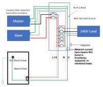
The reason I asked is because if both inverters are bonding the neutral to ground, you should get objectionable current on the EGC (green grounding wire) in battery (inverting mode) with a load. Here is an illustration from another post. Can you measure the current on the purple highlighted areas if this is close to how your system is wired?In bypass mode right now. I don't have a wiring diagram unfortunately
The danger is that if both inverters bond neutral to ground in battery mode, there will be objectionable current flowing in the EGC (green ground wire) as shown in the diagram below.
Neutral-ground bond is shown in light blue. Orange highlight is line current from the top inverter in battery mode to the load (I did not draw the load). Yellow highlight is normal neutral current from the load back to the top inverter. Purple highlight shows the objectionable current with black arrows showing the flow. It travels on the neutral wire to the bottom inverter and then crosses to the EGC via the neutral-ground bond in the bottom inverter. From there it flows on the EGC back to the top inverter's neutral. This objectionable current can be eliminated by removing the bonding screw in the bottom inverter so that there is only one neutral-ground bond in the system.
Here is the diagram without the highlighting.
Lost me.To check for a double n/g connection. You have to measure the ground wire current between the suspected n/g connections.
The AC being supplied to the inverters comes from the subpanel breakers (L1& 2) and ties from the subpanel's N & G terminals (ONLY bonded at the Service Utility point of entry at the Mains Panel.
So, any point from inside those conductor terminations inside the subpanel to/from the Inverters, are just 2 points along the same wires. If there's no current flowing thru ground conductors with the inverters disconnected AND if there's no current flowing thru the ground conductor when the inverters are drawing ONLY solar or batteries; but there IS when inverters are bypassing Utility, then a bonding is occurring within the inverters and will show on clamp meter at the sub panel.
As this equates to 2 points along the same current path, how is this not the right place to measure?
Attachments
Last edited:
timselectric
If I can do it, you can do it.
- Joined
- Feb 5, 2022
- Messages
- 18,807
I think that we're just talking about two different points. When I say "sub panel ", I'm referring to the loads panel. Which is feed from the inverter outputs. I believe that you are referring to a panel that is between the main panel and the inverters. And is used to feed the inverters.Lost me.
The AC being supplied to the inverters comes from the subpanel breakers (L1& 2) and ties from the subpanel's N & G terminals (ONLY bonded at the Service Utility point of entry at the Mains Panel.
So, any point from inside those conductor terminations inside the subpanel to/from the Inverters, are just 2 points along the same wires. If there's no current flowing thru ground conductors with the inverters disconnected AND if there's no current flowing thru the ground conductor when the inverters are drawing ONLY solar or batteries; but there IS when inverters are bypassing Utility, then a bonding is occurring within the inverters and will show on clamp meter at the sub panel.
As this equates to 2 points along the same current path, how is this not the right place to measure?
timselectric
If I can do it, you can do it.
- Joined
- Feb 5, 2022
- Messages
- 18,807
I'm saying that you have to check for current on the ground between the inverter and the main n/g bond.
Anywhere along its path is fine.
Anywhere along its path is fine.
Got ya. I call the subpanel, that which feeds 240 into the inverters and a critical loads panel the load distribution panel being supplied by the inverters. Don't know if that's correct residential terminology...lol.I'm saying that you have to check for current on the ground between the inverter and the main n/g bond.
Anywhere along its path is fine.
I've seen numerous posts wherein DIYers don't use separate sub/load panels (see my modifications to your drawing above). You can do this if an AC Service transfer switch is used electrically. Many DIYers videos on YT just employing a breaker in their Mains panel to supply the inverters out to their loads panel also. I'll have to re-watch the YouTuber's video I first posted, but I believe he is connected thru a shared "subpanel."
Last edited:
timselectric
If I can do it, you can do it.
- Joined
- Feb 5, 2022
- Messages
- 18,807
These terms are interchangeable.
We just weren't on the same page.
We eventually got there, in the end. lol
We just weren't on the same page.
We eventually got there, in the end. lol
LOL...it's all good! Just had a quick look at the video again. He's using a mechanical disconnect on his incoming ac, with common ground carried to his inverters and loads panel. Because he's using the grid to power his inverters, he must do this, as he doesn't constitute a separately derived system. So, when his inverters are connected to the grid and in ac bypass, either his LV6548s or his "loads" are creating the N/G bond. If the LV6548s do NOT create a N/G bond in the Utility (bypass) mode, then his loads are wired wrong, as I don't see a bonding screw in his loads panel. But if, the distributor in the US for MPP was correct today, then it's an issue.These terms are interchangeable.
We just weren't on the same page.
We eventually got there, in the end. lol
Guess I'll just order 2 LV8548s for now and test for myself. If simple removal of bond screw works and adding an AC In/Out jumper, that works vs the price of the Sol-Arks!
timselectric
If I can do it, you can do it.
- Joined
- Feb 5, 2022
- Messages
- 18,807
Definitely agreeLOL...it's all good! Just had a quick look at the video again. He's using a mechanical disconnect on his incoming ac, with common ground carried to his inverters and loads panel. Because he's using the grid to power his inverters, he must do this, as he doesn't constitute a separately derived system. So, when his inverters are connected to the grid and in ac bypass, either his LV6548s or his "loads" are creating the N/G bond. If the LV6548s do NOT create a N/G bond in the Utility (bypass) mode, then his loads are wired wrong, as I don't see a bonding screw in his loads panel. But if, the distributor in the US for MPP was correct today, then it's an issue.
Guess I'll just order 2 LV8548s for now and test for myself. If simple removal of bond screw works and adding an AC In/Out jumper, that works vs the price of the Sol-Arks!
Lt.Dan
Solar Wizard
Keep in mind opening the case will damage the security seal and void warranty. Get written consent from the manufacture first.
eabyrd
Solar Enthusiast
Please see this thread on this issue. The issues Dan ran into had to do with an extra grounding leg. Please be very cautious modifying these units unless you thoroughly understand the purposes of bonding and earthing

 diysolarforum.com
AC side MPP LV6548 connections, critical load panel, wiring
Since posting that video, MPP Solar tech support (Andy Y) has advised me that the bond screw can be removed (and it is safe to do so) on the LV6548 inverter. In your video, around 5:32 lower left, there is what may be a bonding screw with a picture of a screw next to it. Is that the screw you...
diysolarforum.com
Similar threads
- Replies
- 13
- Views
- 600
- Replies
- 3
- Views
- 274
- Replies
- 1
- Views
- 194