diy solar

diy solar

6000XP sub panel question

Subdood

Photon Wrangler
Joined
Mar 27, 2022
Messages
505
Location
NE Kentucky
Hey all, I have an EG4 6500 feeding a critical loads sub panel right now. I have the hot and neutral wires feeding the panel, the hot goes to a single pole of a 70A double pole breaker, the other pole is not connected. The neutral wire is connected to the neutral bar in the panel. Since this a sub panel the neutral and ground bars aren't bonded.

I have not done any upgrades to the firmware on the 6500 since I got the inverter in October '22, and have not removed the N/G bonding screw in the inverter. Because of this, when I transferred the 120V loads to this sub panel from the house panel, I transferred both the hots and neutrals. I did this because the early iterations of the firmware did not create a common neutral.

I am considering upgrading to the 6000XP, which from what I understand, has a common neutral. Is this correct ? Because of this do I need to remove the neutral wires between the main panel and sub panel, and just run the hots? And maybe use a larger wire to connect neutral bars in the main panel and sub panel? Or does it matter?

I should note that this main panel is inside the house but is not bonded N to G as the service panel is outside on the pole and that is bonded.

Thanks
 
Before I answer your question: Will you have a bypass switch to bypass the 6000XP?
 
Hey all, I have an EG4 6500 feeding a critical loads sub panel right now. I have the hot and neutral wires feeding the panel, the hot goes to a single pole of a 70A double pole breaker, the other pole is not connected. The neutral wire is connected to the neutral bar in the panel. Since this a sub panel the neutral and ground bars aren't bonded.

I have not done any upgrades to the firmware on the 6500 since I got the inverter in October '22, and have not removed the N/G bonding screw in the inverter. Because of this, when I transferred the 120V loads to this sub panel from the house panel, I transferred both the hots and neutrals. I did this because the early iterations of the firmware did not create a common neutral.

I am considering upgrading to the 6000XP, which from what I understand, has a common neutral. Is this correct ? Because of this do I need to remove the neutral wires between the main panel and sub panel, and just run the hots? And maybe use a larger wire to connect neutral bars in the main panel and sub panel? Or does it matter?

I should note that this main panel is inside the house but is not bonded N to G as the service panel is outside on the pole and that is bonded.

Thanks
Correct that the 6000XP has a common neutral - it has a neutral bus bar that you connect both the neutral from you main panel to, as well as to connect out to the neutral in your sub panel. The same goes for the grounds. I would say just leave the neutrals for your circuits connected to the sub panel as you already have and make sure the N-G bond is disabled in the 6000XP settings. Having said that, I’m not an electrician - I just pretend to be one once in a while.
 
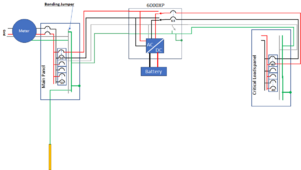
Without a transfer switch I would wire it like this:

View attachment 197709
Thanks, I appreciate it. Do you agree with AZSJ and just leave the neutral wires connected the way they are now? That is, ran from the main panel along with the hots? Or run a common neutral wire (8 gauge?) between the neutral bars on the two panels? Or does it matter?

Am I seeing a 50A DP breaker at the pole and a 40A DP breaker feeding the CL panel?
 
Last edited:
make sure the N-G bond is disabled in the 6000XP setting
Which setting is that? Does this mean that all times, whether on battery/PV power or bypass, there is no N/G bond in the inverter?

I'm guessing 8 awg hot and neutral wires going to and from the inverter?
 
Which setting is that? Does this mean that all times, whether on battery/PV power or bypass, there is no N/G bond in the inverter?

I'm guessing 8 awg hot and neutral wires going to and from the inverter?
Correct - regardless of the mode it is in, the bond in the inverter would be disabled. Since the grounds and neutrals are on common bus bars and connected to your sub panel, the N-G bonding is coming from the main panel at all times.

Interesting question re: the wire gauges. The manual recommends 8awg, but the system also supports 50amp pass through. 8awg isn’t recommended for 50 amp continuous. I wired mine with 6awg and used 50 amp breakers to be safe.
Thanks. I already have 4awg running to and from my 6500, just a hot and neutral in 1in inch PVC conduit. Plus 8awg ground. I don't think I can get another 4ga wire to go thru it, or if it would violate the conduit fill requirements if I added one. Would hate to have to pull all of those 4ga wires and substitute them with 8ga. Seems wasteful.

Edit: According to PVC fill charts, I can run 3x 4 awg plus 1x 8 awg in 1in conduit, so maybe I'll do that. Hope the inverter terminals can accept 4 gauge wire.

Edit #2: if I put in another 6KXP, maybe using the 4ga would be a good idea to run into a raceway box to some kind of junction (Polaris lug?) and then distributed to each inverter from there via 8ga. I might be off on the current carrying capabilities of 4ga, so I'm just scatter shooting here..
 
Last edited:
Thanks. I already have 4awg running to and from my 6500, just a hot and neutral in 1in inch PVC conduit. Plus 8awg ground. I don't think I can get another 4ga wire to go thru it, or if it would violate the conduit fill requirements if I added one. Would hate to have to pull all of those 4ga wires and substitute them with 8ga. Seems wasteful.

Edit: According to PVC fill charts, I can run 3x 4 awg plus 1x 8 awg in 1in conduit, so maybe I'll do that. Hope the inverter terminals can accept 4 gauge wire.

Edit #2: if I put in another 6KXP, maybe using the 4ga would be a good idea to run into a raceway box to some kind of junction (Polaris lug?) and then distributed to each inverter from there via 8ga. I might be off on the current carrying capabilities of 4ga, so I'm just scatter shooting here..
You’ll need two hots coming in and two coming out, so 3 wires for hots won’t be enough.

I like to err on the side of caution and size everything for the full 50 amp pass through capability. That’s very unlikely so 8 AWG will probably be fine. It’s rated for 50 amps but not continuous. I plan to run 1 AWG from a 100 amp breaker in the main panel and using a small 6 slot 100 amp panel as my combiner. Then a 50 amp breaker for each of 2 6000xp’s - 2 x 6 AWG hots to each inverter. I’m planning to combine the outputs in the same way using another small 100 amp panel.
 
You’ll need two hots coming in and two coming out, so 3 wires for hots won’t be enough.
I'm not understanding what you're getting at. I already have two 4awg (one hot, one neutral) coming in and going out of my present inverter. All I would need is another hot wire. I think I can get another 4awg (second hot) for the new inverter run thru the present 1in conduits.
 
I'm not understanding what you're getting at. I already have two 4awg (one hot, one neutral) coming in and going out of my present inverter. All I would need is another hot wire. I think I can get another 4awg (second hot) for the new inverter run thru the present 1in conduits.
Gotcha - I’m dense. For some reason I was thinking you had the inputs and outputs in the same conduit. Have a bit of a flu today is my excuse 😎

As far as I know, 4 AWG won’t fit in the neutral bus bar, but perhaps you could use a lug adapter on it. Even 6 AWG is a little tight. More than likely 4 AWG might fit in the breakers for the hots though, but not totally sure. I guess you’ll find out once you have one on hand. I would check with mine but don’t have any 4 AWG to try.
 
As far as I know, 4 AWG won’t fit in the neutral bus bar, but perhaps you could use a lug adapter on it. Even 6 AWG is a little tight. More than likely 4 AWG might fit in the breakers for the hots though, but not totally sure
Oh, never thought of that possibility. Might have to run the 4awg into a Polaris lug and then run 8awg into the inverter. Just trying to keep the 4awg, it cost me about $1.60/ft. Might put a 6in x 6in x 4ft metal raceway under the inverter to keep it clean.

Did you use ferrules with any of your wires? I know they recommend them on the PV wires.
I did but only on the PV wires.
 
Back
Top