Update….. I had the units in parallel and was only experiencing the sudden loss in power every other day…. Decide to keep just one hooked up while we fogure out the parallel thing. Now that one is consistently throwing fault 8 high bus bar voltage…. Never had that one before


You are using an out of date browser. It may not display this or other websites correctly.
You should upgrade or use an alternative browser.
You should upgrade or use an alternative browser.
MPP-Solar LVX-6048
- Thread starter jasonhc73
- Start date

Swap it out and see if the other one does it. I think Ian will answer texts if you want to try contacting him for support.Update….. I had the units in parallel and was only experiencing the sudden loss in power every other day…. Decide to keep just one hooked up while we fogure out the parallel thing. Now that one is consistently throwing fault 8 high bus bar voltage…. Never had that one before
I change to SUB from SBU and it solve the fault....... but its like the inverter does not like to see grid voltage when charging from solar. BTW I only have 2.2k of solar nothing big for now. (1 string of 6 @ 380w).
I am going to update the firmware first and check if that helps. if not I will switch inverters.
I am going to update the firmware first and check if that helps. if not I will switch inverters.
So you do have grid hooked up?I change to SUB from SBU and it solve the fault....... but its like the inverter does not like to see grid voltage when charging from solar. BTW I only have 2.2k of solar nothing big for now. (1 string of 6 @ 380w).
I am going to update the firmware first and check if that helps. if not I will switch inverters.
Well if a low freq inverter is suppose to have higher surge than he was correct that it is not a true low freq inverter. Both models have the same surge, with or without the giant transformer.Can you tell us more about why you believe the lvx6048 is high freq, split phase transformer aside? I have not opened it up to study the dc to ac conversion but from all I read it is low freq. Interested in learning more
So inverter 1 keep showing this error…. Inverter 2 is 1/3 updated….
I will switch displays once Inverter 2 is done just in case the connection failure has something to do with it.
Ok so switching displays did the trick… will report back how the two in parallel are doing once I complete the firm upgrade


I will switch displays once Inverter 2 is done just in case the connection failure has something to do with it.
Ok so switching displays did the trick… will report back how the two in parallel are doing once I complete the firm upgrade
Attachments
Last edited:

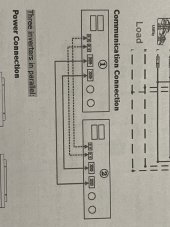
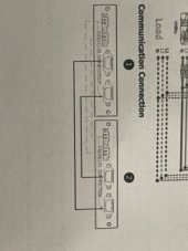
Here are 2 images of the paralleling diagrams 1st image shows instructions on the paralelling kit image 2 is LVX-6048. The vidoe in you tube from Ians solar project went with the first image.
There is a clear difference on how the current wires are connected.
There is a clear difference on how the current wires are connected.
Attachments
good luck!Yeap both update to 6306. Just changed current balance cables to follow image 1 aka Ians connection on youtube.
Stay tuned!
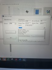
There is definitely a problem when you connect all three inputs. When i turn on grid input to the inverters they get very noisy and i usually will get some sort of fault if i leave it connected during sunlight hours.Bad luck… went to check and found one inverter in a fault. Same one that was faulting before…. There is something with grid, batteries and solar that it doesn't likes. The other inverter does no have solar and no faults. View attachment 114611
I have been running mine like image 2. Let us know if using the other schematic made a differenceHere are 2 images of the paralleling diagrams 1st image shows instructions on the paralelling kit image 2 is LVX-6048. The vidoe in you tube from Ians solar project went with the first image.
There is a clear difference on how the current wires are connected.
Today we will know. I am not at home but will monitor remotely thru Solar Assistant. I was running it like image 1 ( according to the paralleling kit) until I saw the lvx-6048 manual. During that period I had no issues other than the random reset or loss of power with all three sources connected.
Ian you are still running it in parallel, correct?
Ian you are still running it in parallel, correct?
iamrich
Solar Addict
You would have to open the unit to verify (I am not opening my twoCan you tell us more about why you believe the lvx6048 is high freq, split phase transformer aside? I have not opened it up to study the dc to ac conversion but from all I read it is low freq. Interested in learning more
") ), but I am betting there is a bunch of mosfets doing the conversion and then dumping the power into the auto transformer to keep everything balanced. I doubt the conversion board is full of LF transformers.
), but I am betting there is a bunch of mosfets doing the conversion and then dumping the power into the auto transformer to keep everything balanced. I doubt the conversion board is full of LF transformers.I am not an inverter engineer, so take this with a grain of salt...
I am running in parallel. I normally have 3, but one is dead right now. There is a direct short between the battery connections on the main board that faults out the batteries.Today we will know. I am not at home but will monitor remotely thru Solar Assistant. I was running it like image 1 ( according to the paralleling kit) until I saw the lvx-6048 manual. During that period I had no issues other than the random reset or loss of power with all three sources connected.
Ian you are still running it in parallel, correct?
Ok, don't chew me out here ok?
I know it isn't safe...but the last two weeks my single unit has been running flawlessly, only after lifting the ground of the inverter out put to the sub panel. My unit is mounted in a metal quonset hut building, everything is basically bonded to ground. My house is old and so is the grid service entrance (old square D QO) I know I have more than one spot where N is bonded to G but I would have to tear everything out and start over to fix it. (the old half of the house is an old 2 wire system, no ground wire among other issues...) Landing the G from the inverter was causing all sorts of headaches; flickering lights, high bus faults, inaccurate readings on the solarpower app, funny humming/rattling noises from the inverter, ect... I tried the capacitor trick nc73 was telling us about, I tried 14uF, 16uF, even a 50uF capacitor on both the grid and inverter side L1-L2... no change, it didn't help. When you guys started talking about the current sensing wires for your parallel units, I half way wondered if the ground loop is what is confusing our inverters. If the current sensors are picking up transient currents because of the ground loop issues, then the control circuit would go haywire causing all sorts of problems. This is just me thinking out loud again, hoping we might figure something out...
I know that it has been discussed extensively all over, but there still seems to be confusion on the subject of the N-G bond inside our inverters. I would like to get a second LVX6048 and run them in parallel, but it seems that no one has figured it out yet, and so I am hesitant to do it.
I know its not safe to run equipment without a ground, but for testing purposes, it might be worth a try....
@ Ian30, Insulso1, and Boondox and your stepson, have you guys tried running your units in parallel without the GROUND landed?
please don't try it if you don't feel safe doing it!
Similar threads
- Replies
- 7
- Views
- 935
- Replies
- 0
- Views
- 202
- Replies
- 8
- Views
- 2K