diy solar

diy solar

DIY inverter software upgrade to combat heavy shading

This is slightly like being at work where we were always chewing the cud on the why's and wherefores of different ways of doing things, an enlightening experience :)

Indeed it is !

In later years before retirement, I was usually just one very small part of a large design team. Always enjoyed the weekly planning meetings.

I left the magic and mystery to the IT guys, and was very glad to do that.
They in turn left me to solve my own problems of electrical noise and EMC compliance, thermal design, serviceability, and creating something that could actually be manufactured.
Always plenty to do and think about, without worrying about software bugs and the really weird esoteric stuff.
And the magicians were happy to let me play with my more practical toys.

We even had industrial designers and some "arty" type people, and even at one stage a very strange professional genius mathematician.
He was a classic character, odd socks, wild hair, and he could do in his head in minutes what would have taken the very best of us hours with a scientific calculator, even if we could understand how to even go about solving the problem.

Its absolutely amazing what a friendly team of specialists, with some overlapping skills, can achieve.
 
Last edited:
The TI 320F28XX DSP series is somewhat tolerant of break points and if there is external current protection can clear the gpio pins to prevent this. The F28 series is used in the XW products, still used today in hybrid inverters I've worked with.
 
It's a simple 1 pole low pass filter, well known in DSP circles so I dont see the point of your question, perhaps you need to invest in a book on DSP principles. I have many many filters of different sorts in my code.

I'm not asking because I don't know, rather to point out how many transistors and how many CPU cycles are required to perform the same function.

I have seen a design where someone assigned didn't know how to spell "DSP" and failed to attenuate out of band signals with their digital implementation. Had they known what they were doing, they could have met spec. "Linear Systems" or digital signal processing was my worst class, but I could still see frequency response of their implementation (sub-sampling and averaging) and of the legacy system in my mind's eye. Uphill battle to show it was inadequate but I eventually forced a change.

At low frequency (e.g. 60 Hz), CPU or state machine, PWM for a power circuit, is very efficient. Discrete L and C would be huge for power, but I've used them for millisecond to seconds time constant control signals and filtering.

For higher frequencies, considerable IC real estate and cycles are expended, but passive RC or an op-amp circuit is easy.

Some 25 years ago, a cell phone had 100 man-years of code in it. Of course, when a model sells 100,000,000 units (or code is reused in that many), it is cost effective.

I figure these days it takes 2 billion transistors running at 2 GHz to accomplish what the previous generation did with 7 triodes.

1671741842891.png 1671741878203.png

Today I use Matlab for instrument control and data analysis. The real-time functions occur in the instruments. When I was designing a product (RGA or atomic mass spectrometer), my circuits were mixed signal and either commanded from my PC or by the microcontroller firmware guys programmed. They eventually used a Snapdragon CPU and an NXP microcontroller. I had the system running on my bench before there was any software or firmware support.
 
And magnetic amplifiers. I succeeded in implementing one from a couple transformers, similar to shown in a link at bottom of post below.
Not very nicely behaved; apparently need different magnetic characteristics for the core.

As an added bonus, they will be EMP hard.

 
I'm not asking because I don't know, rather to point out how many transistors and how many CPU cycles are required to perform the same function.

I have seen a design where someone assigned didn't know how to spell "DSP" and failed to attenuate out of band signals with their digital implementation. Had they known what they were doing, they could have met spec. "Linear Systems" or digital signal processing was my worst class, but I could still see frequency response of their implementation (sub-sampling and averaging) and of the legacy system in my mind's eye. Uphill battle to show it was inadequate but I eventually forced a change.

At low frequency (e.g. 60 Hz), CPU or state machine, PWM for a power circuit, is very efficient. Discrete L and C would be huge for power, but I've used them for millisecond to seconds time constant control signals and filtering.

For higher frequencies, considerable IC real estate and cycles are expended, but passive RC or an op-amp circuit is easy.

Some 25 years ago, a cell phone had 100 man-years of code in it. Of course, when a model sells 100,000,000 units (or code is reused in that many), it is cost effective.

I figure these days it takes 2 billion transistors running at 2 GHz to accomplish what the previous generation did with 7 triodes.

View attachment 125852 View attachment 125853

Today I use Matlab for instrument control and data analysis. The real-time functions occur in the instruments. When I was designing a product (RGA or atomic mass spectrometer), my circuits were mixed signal and either commanded from my PC or by the microcontroller firmware guys programmed. They eventually used a Snapdragon CPU and an NXP microcontroller. I had the system running on my bench before there was any software or firmware support.
I see what you mean, some call that progress, others not. I use the tools of the time at my disposal and were it not for the level of integration the project would have been impracticable given my limited resources.
 
It will be interesting to see what happens when Taiwan goes off line, and stops producing all our chips.
Its bad enough now.
Maybe it will have to go back to designing things with discrete transistors and triodes.
I think we will be down to design by what we have in our boxes of junk/stock/spares, certainly for the more esotoric parts but as I discovered recently even once common power mosfets have become unobtanium so a lot of time will have to be spent characterizing a design with alternate parts or perhaps buying stock for a prospective design before it's even off the drawing board!

********************************AND FINALLY MERRY XMAS EVERYONE******************************

PS Dear father Xmas can I have a box of unobtainable parts please hahaha
 
Last edited:
I see what you mean, some call that progress, others not. I use the tools of the time at my disposal and were it not for the level of integration the project would have been impracticable given my limited resources.

Sometimes, "newer, faster, better, cheaper" with digital delivers a worse implementation, sometimes better.

Digital implementations bring certain capabilities and performance.
Digital broadcast and communications is compressed, occupies less bandwidth, allowing parts of the spectrum to be sold off.
With CDMA, multiple transmitters can occupy same portion of spectrum, and can vary in how much of its capacity is consumed.
The radios are software defined, digitizing the spectrum which is then processed by DSP, and can be updated. Over the air.

For power and analog functions, what might have required manual tuning by trim pots or rework can be accomplished under software control. manufacturing becomes more automated.
Same thing is showing up in instruments. My HP 8753C network analyzer uses a cal kit consisting of open/short/50ohm/thru. The new way is a box with two or four ports that cables connect to, and it is commanded to switch into various impedance states. Not those pure values, I assume, but whatever they are is stored in NVM, and calibration is completed without moving cables.

Your inverter design could be relatively dumb and mostly open loop, or it could be adaptive to loads and conditions. UL-1741 and -SA inverters drive test signals for anti-islanding, and can do grid support with reactive currents, maybe power-factor correction too.

Does your inverter behave well with inductive loads that draw current and return it out of phase?
I think my Sunny Island does pretty well, with actual W consumption not increasing as much as the VA I calculate when connecting some transformers. A UPS at work I used to drive an isolation transformer reported tripling of load VA and drew enough from AC input to trip breaker (which also powered a pump.) I don't have hard numbers on the power and current involved, just saw UPS output increase from 350 VA to 1000 VA.

Tools at our disposal, I know Matlab can be used to do great things (built into high performance oscilloscope, used to perform signal processing and then download into FPGA for final product) but I don't know how to use it for real-time. Just an alternative to LabView and other languages.
 
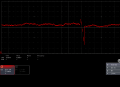
Re-installed & working but the weather is foul, overcast & raining hence no shadows to play with but the following scope shot (PV volts) shows it doing a scan (big voltage spike) with mppt activity both sides of it. As can be seen the scan selects a voltage very close to what mppt is already operating at and after the scan mppt soon fine tunes it back again. This is because the scan is in fairly big 5V steps to reduce elapsed scan time so as expected is only a rough approximation to where the highest power peak actually is.
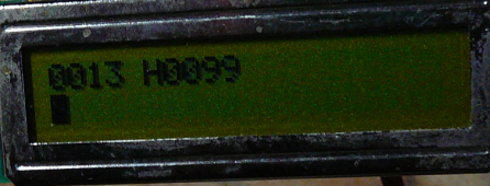
The LCD display is for debug, top row is watts, then mode (H for water heating) then volts, bottom row is for panic messages!
mppt_scan_rain_281222.pngwatts_volts_rain_281222.png
 
This type of constant voltage behavior of a "smart" mppt algorithm, is what originally started me thinking about a simple analog based controller.

Just a conventional garden variety pwm switching power supply control chip, driving a buck converter to maintain a constant voltage across the solar panels, and therefore optimum solar panel loading from twilight to a clear blue sky is all you really need.
And it cannot lock onto false peaks caused by shading either. And it responds super fast to passing clouds.

I have now built a few of this type of "analog brain" type of solar controller, and made some back to back comparisons with a proper commercial software driven controller.

My conclusions are that under truly appalling conditions, like 15 watts from a 300 watt panel, a software driven algorithm is better.
You might find a whole extra 5 to 7 watts on a truly awful day.

But in the great overall scheme of things, that small advantage makes absolutely no difference.
In more typical solar conditions, the simple analog controller responds faster, cannot get lost, and is indistinguishable in overall efficiency.
https://diysolarforum.com/threads/simple-home-made-analog-mppt-contoller.47057/
 
Last edited:
This type of constant voltage behavior of a "smart" mppt algorithm, is what originally started me thinking about a simple analog based controller.

Just a conventional garden variety pwm switching power supply control chip, driving a buck converter to maintain a constant voltage across the solar panels, and therefore optimum solar panel loading from twilight to a clear blue sky is all you really need.
And it cannot lock onto false peaks caused by shading either. And it responds super fast to passing clouds.

Constant voltage could be the wrong peak, for the case of 12s2p if several panels of one string are shaded.
Or a single string 12s of half-cut panels which are internally wired as parallel (likely 3p2s) so the entire string is 3p36s.
MPPT needs to find lower voltage higher current higher power peak.
 
If you have 12s 2p, if several panels in one string are shaded, then that becomes a "sick" string.
The other unshaded string should be working quite normally at the correct peak power voltage.

Assuming the sick string and healthy string are coupled together through series diodes, the healthy string will still be functioning normally, and the sick string will be pretty much out of the picture.

Ideally two parallel connected strings should each have its own solar controller, of whatever type....
That is what I am working towards. They are pretty cheap and easy to make, now I have something that I know works pretty well.
 
This type of constant voltage behavior of a "smart" mppt algorithm, is what originally started me thinking about a simple analog based controller.

Just a conventional garden variety pwm switching power supply control chip, driving a buck converter to maintain a constant voltage across the solar panels, and therefore optimum solar panel loading from twilight to a clear blue sky is all you really need.
And it cannot lock onto false peaks caused by shading either. And it responds super fast to passing clouds.

I have now built a few of this type of "analog brain" type of solar controller, and made some back to back comparisons with a proper commercial software driven controller.

My conclusions are that under truly appalling conditions, like 15 watts from a 300 watt panel, a software driven algorithm is better.
You might find a whole extra 5 to 7 watts on a truly awful day.

But in the great overall scheme of things, that small advantage makes absolutely no difference.
In more typical solar conditions, the simple analog controller responds faster, cannot get lost, and is indistinguishable in overall efficiency.
https://diysolarforum.com/threads/simple-home-made-analog-mppt-contoller.47057/
Doesn't look very "constant voltage" to me, however as illustrated by the simulation plot at the beginning of this thread this particular array's MPP voltage can vary between ~30V & ~120V depending upon conditions so no kind of "constant voltage" controller would be suitable, I don't think gaining a few watts is anywhere near a true appreciation of the losses. I have a particular reason for trying to maximize efficiency as I can neither add more panels nor improve the location so the subject of this thread is the only possibility open to me.
 
If you have 12s 2p, if several panels in one string are shaded, then that becomes a "sick" string.
The other unshaded string should be working quite normally at the correct peak power voltage.

Assuming the sick string and healthy string are coupled together through series diodes, the healthy string will still be functioning normally, and the sick string will be pretty much out of the picture.

Ideally two parallel connected strings should each have its own solar controller, of whatever type....
That is what I am working towards. They are pretty cheap and easy to make, now I have something that I know works pretty well.
I think 2p is a rather different case to mine (being 4s) however generally for example if half the array is shaded the electronics should be such as to abstract half the peak power etc. There are occasions when the additional cost of the electronics outweigh the cost of additional panels if one has infinite space to put them but that is not my situation.

I have also looked at per panel optimisers but the cost of the electronics together with waterproofing makes them un-economic in my situation, there is also the potential for a per panel boost wire-ored to a common bus but again the cost is high IMOP. There doesnt seem to be much point in looking around for good deals on panels only to double there cost with some added gubbins, after all just mounting systems alone are quite enough so I am still a fan of one central converter.
 
Last edited:
Doesn't look very "constant voltage" to me, however as illustrated by the simulation plot at the beginning of this thread this particular array's MPP voltage can vary between ~30V & ~120V depending upon conditions so no kind of "constant voltage" controller would be suitable, I don't think gaining a few watts is anywhere near a true appreciation of the losses. I have a particular reason for trying to maximize efficiency as I can neither add more panels nor improve the location so the subject of this thread is the only possibility open to me.
You missed the point entirely.
That massive 30v to 120v swing only occurred during the time the mppt software was doing a full range sweep.
While the mppt function was doing its normal constant tracking job, the voltage hardly changed.

If you only have one series string, and there is shading, output power is going to drop significantly no matter what kind of controller you have.
Its quite likely you are right though, that a software algorithm will follow the voltage down and beat a constant voltage controller, although you might be surprised how uncritical the actual panel voltage is.

Where you have multiple parallel strings fitted with series diodes, if the voltage in one string drops significantly due to shading, the diode for that string effectively isolates the shaded string. The unshaded strings will carry on normally at their usual full max power operating voltage.

The idea that the controller will then overload the unshaded panels somehow to pull down the total voltage to be the same as the shaded panel is not going to happen.
Basically if you have parallel strings sharing the same controller and one string is shaded, you effectively lose the whole shaded string as far as power output goes.

The ideal solution would be to have one software tracking mppt controller for EACH series string, but that gets expensive.
A lame shaded string might then be able to contribute something, without effecting the other fully functional strings.
 
You missed the point entirely.
That massive 30v to 120v swing only occurred during the time the mppt software was doing a full range sweep.
While the mppt function was doing its normal constant tracking job, the voltage hardly changed.
Nope, you are to blinkered by your constant voltage approach!
The plot I referred to was the 1st plot in the thread NOT the scope shot.
The first plot in the thread shows power vs voltage for a partially shaded SERIES array.
I would also mention I don't think you understand the purpose of MPPT, the reason the voltage is not varying much is that the ambient conditions are not changeing much for the duration of the shot (several minutes) as the sky was universally dull & overcast, it's action is much more pronounced on a sunny but cloudy day particularly when clouds pass in front of the sun. The whole point is it finds the MPP dynamically with NO POT TWIDDLING!
If you only have one series string, and there is shading, output power is going to drop significantly no matter what kind of controller you have.
Its quite likely you are right though, that a software algorithm will follow the voltage down and beat a constant voltage controller, although you might be surprised how uncritical the actual panel voltage is.
Not true! To extract maximum power from a partially shaded series array the voltage has to be highly agile as once again the FIRST POST shows.
Where you have multiple parallel strings fitted with series diodes, if the voltage in one string drops significantly due to shading, the diode for that string effectively isolates the shaded string. The unshaded strings will carry on normally at their usual full max power operating voltage.

The idea that the controller will then overload the unshaded panels somehow to pull down the total voltage to be the same as the shaded panel is not going to happen.
Basically if you have parallel strings sharing the same controller and one string is shaded, you effectively lose the whole shaded string as far as power output goes.

The ideal solution would be to have one software tracking mppt controller for EACH series string, but that gets expensive.
A lame shaded string might then be able to contribute something, without effecting the other fully functional strings.
Although this thread has often wandered off the point I emphasise this proposed solution & work has nothing whatever to do with parallel strings so please do not refer to them in any comments. Let me make it clear again my array and solution is a SINGLE SERIES STRING. If you have some other problem & solution perhaps you might start a new thread for it.
 
Last edited:
O/k lets limit this to people that only run one series string per mppt controller.
I agree with you, that is definitely the optimum.
Provided of course the shaded string still has enough voltage available to charge the battery.

But most of us require more power than just one series string, and that is where your argument breaks down.
A single controller simply cannot adjust for parallel strings that become hugely unbalanced through partial shading of one string.
That is the reality.
 
Last edited:
O/k lets limit this to people that only run one series string per mppt controller.
I agree with you, that is definitely the optimum.
Provided of course the shaded string still has enough voltage available to charge the battery.
Battery ??? Don't have one of those, my primary load is a 3Kw/240V water heater, so I store my energy as hot water.
But most of us require more power than just one series string, and that is where your argument breaks down.
If I needed to I could go 6Kw in a single string within the easily available tech (MOSFETS). More than that and I would have to dust off the thinking cap :LOL:
A single controller simply cannot adjust for parallel strings that become hugely unbalanced through partial shading of one string.
Absolutely spot on, multiple MPPT's is the only way to go with multiple strings, that could be achieved by multiple single input converters (if they play nicely together on the load side) or one converter with multiple MPPT's (there are some around but not all multiple input converters are true multiple MPPTs).

So to recap what I am trying to achieve here is a work around for a problem common to many power tracking algorithms and that is they can lock onto the wrong (not the highest) power peak when faced with a partially shaded string. If and when the sun ever comes out again I will be able to test it in anger, for the time being at least I can see it doesn't misbehave in low light conditions.
 
Haha, I ran without a battery for quite some time, and even without a solar controller for a while.
My home brew inverter is very forgiving regarding dc input voltage, a water heater would be even less fussy.

But most people here run multiple parallel connected strings to charge a battery, which changes the requirements rather a lot.
So what you are trying to do is kind of unique.

The whole false peaks problem , as far as I can see, can only be resolved by doing a sweep of pwm over the whole likely operating envelope.
That would be complicated by the large energy storage electrolytic required between the panels and the buck converter.
The sweep would need to be kept reasonably slow, and even that might get confused by tree branches swaying in the wind, for example.

One very large series string poses some rather intractable problems with partial shading.
With really chronic shading, the inverse diodes are supposed to bypass current around a panel, or sections within a panel that are not contributing.

But as we all know, this creates some very peculiar effects with false peaks when the shading is not quite enough to turn the shunt diodes completely on.

Even if some kind of clever circuit was fitted to each panel to somehow replace this simple shunt diode behavior somehow with an algorithm, I doubt if it could ever be made to work properly.

After thinking about it for a while, my first attempt at this might be to split up the series string into completely separate isolated panels.

Fit an individual mppt algorithm to every panel, coupled to an individual boost converter to step up the single panel voltage to drive the water heating element directly. Some testing could be done with just one panel contributing to what you already have.
The eventual system would have each panel contributing individually and independently to the resistive heating load.

It should not be too difficult to measure dc voltage and current at the panel, and establish a suitable duty cycle from a perturb and observe algorithm. A discontinuous boost converter does not care what the dc output voltage is, it just transfers power into a load. The voltage across the heating element is going to vary widely, and the boost converter does not care. Its totally different to an almost constant voltage battery charging load.

There may be a better solution to all this, but its the only practical solution I can think of right now that does not introduce more problems.
 
Back
Top