Warpspeed
Solar Wizard
This caries on from the "Open source microconverter" thread which I am very guilty of hijacking.
What follows is a home project to build a really simple low cost solar mppt controller that does not involve any software or a microcontroller.
This all started as a bit of an experiment, and it has proven to work much better than I expected, it just uses a simple readily available pwm controller chip to maintain a fixed voltage at the solar panels, and charge a battery up to a fixed final charging voltage.
The charging profile is much better suited to a lithium battery rather than to lead acid.
Its a really basic simple no frills solar charge controller, but it has the advantage of being very easy to get going, and would be very simple to fault find and repair. It has proven to work just as well as a commercial perturb and observe software driven charge controller. If there are any differences in measured performance they would be absolutely minimal in practice.
The idea is that the pwm duty cycle is adjusted to increase as the solar voltage increases. That continually adjusts the loading on the solar panels to hold the panel voltage at the maximum power voltage. It works from dawn to full sun in a clear blue sky, and tracks the max power voltage which is set by a potentiometer.
The rating plate voltage on the panel will tell you where to set the optimum voltage to do this. But if you don't know that, its simple to just tweak the voltage up and down while watching the charging current during bulk charge. A definite maximum in charging current will be found, but its more of a very shallow hump than a sharp peak.
While its true that the optimum solar voltage will vary slightly with temperature and insolation, it will never be very far from the voltage on the rating plate.
All a perturb and observe algorithm does is find this peak through searching. If you know where the peak is, you can just set a potentiometer to that voltage and leave it there. The power fall off either side of the cusp of the power hump is absolutely minimal. Far less than i expected.
The other side of this is the output voltage of the solar controller can be set to the required final battery charging voltage. It will bulk charge up to that voltage, then the current will taper back to zero in the usual expected way.
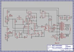
The pwm controller has two proper error amplifiers, which makes it a bit unusual among most other pwm controller chips. Whichever error amplifier requires the greatest reduction in duty cycle takes over control, and crossover is very smooth.
I have had this running for about a month beside a couple of Make Sky Blue commercial perturb and observe controllers, and it appears to be every bit as good in all conditions.
Here is the schematic:
What follows is a home project to build a really simple low cost solar mppt controller that does not involve any software or a microcontroller.
This all started as a bit of an experiment, and it has proven to work much better than I expected, it just uses a simple readily available pwm controller chip to maintain a fixed voltage at the solar panels, and charge a battery up to a fixed final charging voltage.
The charging profile is much better suited to a lithium battery rather than to lead acid.
Its a really basic simple no frills solar charge controller, but it has the advantage of being very easy to get going, and would be very simple to fault find and repair. It has proven to work just as well as a commercial perturb and observe software driven charge controller. If there are any differences in measured performance they would be absolutely minimal in practice.
The idea is that the pwm duty cycle is adjusted to increase as the solar voltage increases. That continually adjusts the loading on the solar panels to hold the panel voltage at the maximum power voltage. It works from dawn to full sun in a clear blue sky, and tracks the max power voltage which is set by a potentiometer.
The rating plate voltage on the panel will tell you where to set the optimum voltage to do this. But if you don't know that, its simple to just tweak the voltage up and down while watching the charging current during bulk charge. A definite maximum in charging current will be found, but its more of a very shallow hump than a sharp peak.
While its true that the optimum solar voltage will vary slightly with temperature and insolation, it will never be very far from the voltage on the rating plate.
All a perturb and observe algorithm does is find this peak through searching. If you know where the peak is, you can just set a potentiometer to that voltage and leave it there. The power fall off either side of the cusp of the power hump is absolutely minimal. Far less than i expected.
The other side of this is the output voltage of the solar controller can be set to the required final battery charging voltage. It will bulk charge up to that voltage, then the current will taper back to zero in the usual expected way.
The pwm controller has two proper error amplifiers, which makes it a bit unusual among most other pwm controller chips. Whichever error amplifier requires the greatest reduction in duty cycle takes over control, and crossover is very smooth.
I have had this running for about a month beside a couple of Make Sky Blue commercial perturb and observe controllers, and it appears to be every bit as good in all conditions.
Here is the schematic: