diy solar

diy solar

How do I connect battery banks that are in 2 different locations (distances) to the one source & keep them evenly balanced

YOTA

New Member
Joined
May 27, 2022
Messages
38
Hello fellow electric wizards - one question I’m struggling to wrap my head around.
I’m sure it’s straight forward for someone.

I have x2 banks @24v (made up of eve 280amp lithium cells)
So that means x2 bms. (Overkill solar 24v)
One bank is very close to the
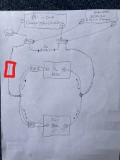
“all in one solar/inverter unit”
The other is 1.5m away.

Now to connect them right so they charge & draw balanced is the question: how ?
With one being close to the source other at a 1.5 m distance.

I’ve drawn a diagram to visually explain.
My confusion lies mainly with. The negative cable.

Do I connect both batterys togther via a solid negative wire. Direct from battery terminal to battery terminal.
Or do I Conect them via the output of the bms.

In my drawing I have option 1 on the left option 2 on the right.

IMG_2125.jpeg

And yes I also have x1 shunt (not shown in drawing) where should attach the shunt ?
Assuming I’m planing on using the x1 shunt for both the batterys (treating both these batterys as a complete system) remaining 24v
Thanks in advance for your advice
 
Consider the BMS part of the battery and the decision becomes obvious. Connect the BMS negative output. Nothing bot the BMS should connect directly to the cells (well, on the negative)

The shunt should go between the bus bar and all loads/chargers. On your drawing, on the single line between the bus bar and inverter.
 
separate equal length cables from both batteries to the bus bar all 4 cables the same length
put the shunt after the bus bar on the negative side and connect it to a second bus bar where all connections for the negative side will be made
 
You did not specify the wire gauges.
Anyway, the battery farther away will be slower to charge due to wire resistance. It will lag to charge and discharge. As the nearer battery tops up the farther one will still be charging. It could work well, just a reduction in capacity.
A lot depends on the charger. Bulk Timeout setting. Float voltage 13.6v vs none.
 
Consider the BMS part of the battery and the decision becomes obvious. Connect the BMS negative output. Nothing bot the BMS should connect directly to the cells (well, on the negative)

The shunt should go between the bus bar and all loads/chargers. On your drawing, on the single line between the bus bar and inverter.
Okay so to make sure I understood properly. You’re saying not to connect the negatives of the battery terminals. With a solid wire.

Instead. Connect the negatives via both bms outputs. (Like in drawing 2)

And shunt goes on the negative also ?
 
Last edited:
separate equal length cables from both batteries to the bus bar all 4 cables the same length
put the shunt after the bus bar on the negative side and connect it to a second bus bar where all connections for the negative side will be made
Battery one is right up against my charge controller/inverter. Like literally 30cm

Battery two is more than 1.5meters away,..

It would seem ridiculous to have 1.5meters of cables wound up to connect the first battery that’s right nexto the charge unit.

All this just to keep an even charge
 
Battery one is right up against my charge controller/inverter. Like literally 30cm

Battery two is more than 1.5meters away,..

It would seem ridiculous to have 1.5meters of cables wound up to connect the first battery that’s right nexto the charge unit.

All this just to keep an even charge
There must be a better way than just having a huge coil of wire sitting there.

What I’m attempting to do is in theory connect both batterys . As one

And pull from opposite ends

- & +
 
Consider the BMS part of the battery and the decision becomes obvious. Connect the BMS negative output. Nothing bot the BMS should connect directly to the cells (well, on the negative)

The shunt should go between the bus bar and all loads/chargers. On your drawing, on the single line between the bus bar and inverter.
& ok so to get the balance right. I would ideally want the cables coming from both the bms outputs to both be the same length cable to a bus bar say for example distance wise located in the middle of the two battery banks. Then from this bus bar a single line black ( - ) wire to my shunt & then to the charge controler
 
So in this situation, what I would do is put a breaker on the (+) wire between (each ) battery and a common bus bar.

Example https://www.bluesea.com/products/category/14/30/Circuit_Breakers/187-Series

I would also feed the charger(s) to the same bus bar with breakers so that they can be shut off and isolated for maintenance.

Keep in mind that the goal is to match impedance for each parallel battery pack. Having identical wire lengths and sizes is one way to achieve this but not the only way. For instance - you could calculate the impact of having a thicker cable on one pack than the other and see if that can work.
 
I have two 48 volt strings of 16 cells in the same box. Was very meticulous to make everything identical between the two. I suppose I could have documented the IR of each cell and done a better job of making each string more equal but didn't. I'm sure there are slight differences in the individual BMS for each string as well. It's extremely difficult to make everything exactly the same, and if you do achieve perfect balance, it's more luck than anything else. As it is, I have one string the leads by about 5% and the other one catches up in the middle of the discharge curve,then overtakes the first one farther down the slope. The same is true when charging. It still works out and I get full capacity of each. 1.5 meters isn't really that much, I'd just build it and see what you get.
 
Yes, drawing two is the correct way to do it for the negative. The positive side drawn in #2 is going to make the situation for the second battery worse. Both positive and negative should go to bus bars. But that still won't even out the charge/discharge between the two batteries.

I suppose you could do the diagonal wiring connection for the two parallel batteries and ditch the bus bars completely. There's plenty of tutorials here in that. When the talk about connection to the negative terminal, the BMS is part of the battery, connect to BMS negative.

Shunt needs to go on the single cable connected to the inverter/loads/charge controller negative. All current must flow through the shunt. Your drawings only show a charge controller. Do you have an inverter or DC loads?
 
Updated drawing - to have both negative & positive cables at same length. Does this look like an option that will work?

And my bcdc alternator charging sett up correctly ?
 
So in this situation, what I would do is put a breaker on the (+) wire between (each ) battery and a common bus bar.

Example https://www.bluesea.com/products/category/14/30/Circuit_Breakers/187-Series

I would also feed the charger(s) to the same bus bar with breakers so that they can be shut off and isolated for maintenance.

Keep in mind that the goal is to match impedance for each parallel battery pack. Having identical wire lengths and sizes is one way to achieve this but not the only way. For instance - you could calculate the impact of having a thicker cable on one pack than the other and see if that can work.
Yes I have a 200amp fuse on the positive line from battery terminal & there is also a big 2 poll dc breaker switch before the lines attach to my “all in one unit” is a 24v 3kw version.
 
Your shunt is worthless. It can't measure the "24 v" accessories, or the alternator charger. Your easiest and most accurate solution is to rely on the readings from the Overkill BMS. You can go fancy and use Solar Assistant with the Uart converters in place of the bluetooth modules on the BMS, or go cheap and use the Liontron Multi app on your iPhone to simultaneously monitor the two BMS's.
 
Your shunt is worthless. It can't measure the "24 v" accessories, or the alternator charger. Your easiest and most accurate solution is to rely on the readings from the Overkill BMS. You can go fancy and use Solar Assistant with the Uart converters in place of the bluetooth modules on the BMS, or go cheap and use the Liontron Multi app on your iPhone to simultaneously monitor the two BMS's.
That’s what I thought , but I’ve been convinced otherwise that the shunt will give me a more accurate reading.. rather than relying on my “all in one unit” or the overkill bms app.
 
I
Your shunt is worthless. It can't measure the "24 v" accessories, or the alternator charger. Your easiest and most accurate solution is to rely on the readings from the Overkill BMS. You can go fancy and use Solar Assistant with the Uart converters in place of the bluetooth modules on the BMS, or go cheap and use the Liontron Multi app on your iPhone to simultaneously monitor the two BMS's.
If I put the shunt in particular position in the sett up can it measure also the accessories / alternator input ?
 
If you put your shunt here, it will see current in and out of the batteries. It will not tell you where the current is coming from or going to in relation to the accessories, inverter, and alternator, but it will give you an accurate SOC
 

Attachments

  • 1drawing.jpg
    1drawing.jpg
    263.7 KB · Views: 4
Back
Top