I was just watching some videos, and came across with this:
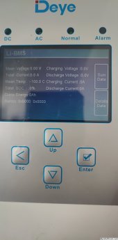
I noticed, the guy connected the RS485 cable to the WNT #2. I'm not sure if that works on RS485, I tried to do the same thing with CAN yesterday, and I had the same false reading (Temp -100C etc). In theory it shouldn't matter, but CAN only works from WNT #1 in my case.


You are using an out of date browser. It may not display this or other websites correctly.
You should upgrade or use an alternative browser.
You should upgrade or use an alternative browser.
Daly Smart Bms Deye inverter CAN communication
- Thread starter signo82
- Start date
Thanks for the video. I don't have a WNT board, as Siji wrote here that communication works directly from the DALY BMS CAN/RS485 port, I can't get the communication to work. I only have 1 battery pack (16s)I was just watching some videos, and came across with this:
I noticed, the guy connected the RS485 cable to the WNT #2. I'm not sure if that works on RS485, I tried to do the same thing with CAN yesterday, and I had the same false reading (Temp -100C etc). In theory it shouldn't matter, but CAN only works from WNT #1 in my case.
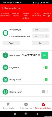
To allow Deye 5kw to communicate with Daly bms using protocol rs485 I did the below few steps:
1- On the deye inverter I set lithium mode to 12.
2- Using DalyBmsMonitor, under engineering model inverter set to Deye, protocol= RS485.
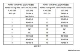
3- I used a straight RJ45 cable to connect my Daly WNT board, rs485 port to my Deye BMS rs485 port.
Hi,
thank you.
This finally worked for me (I use the first RJ45 port on WNT board)
Now there are other problems.
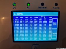
Temperature reading is ok, but SOC not.
Bms SOC is different from Inverter SOC. So witch one is used for manage the inverter behaviour?
If I change BMS SOC from Daly PC software it change on BMS SOC side, but inverter still show old value.
Then if I disconnect RJ45 cable, inverter doesn't stop working, making system very unsafe.
Have you same issues?
Thank you all.
Attachments
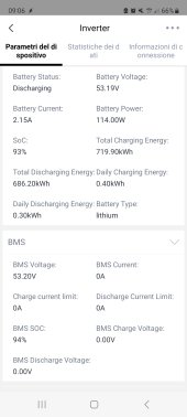
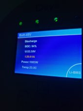
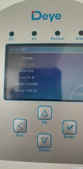
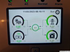
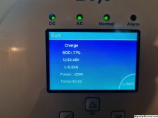
Hi, Keep the BMS communicating with the inverter overnight and you will have same SOC on Daly and Deye, in addition to other value that will appear on Deye screen. But the current you see on Deye (-191) is weird.Hi,
thank you.
This finally worked for me (I use the first RJ45 port on WNT board)
Now there are other problems.
Temperature reading is ok, but SOC not.
Bms SOC is different from Inverter SOC. So witch one is used for manage the inverter behaviour?
If I change BMS SOC from Daly PC software it change on BMS SOC side, but inverter still show old value.
Then if I disconnect RJ45 cable, inverter doesn't stop working, making system very unsafe.
Have you same issues?
Thank you all.
yes it seem x10 191 instead of 19,1AHi, Keep the BMS communicating with the inverter overnight and you will have same SOC on Daly and Deye, in addition to other value that will appear on Deye screen. But the current you see on Deye (-191) is weird.
I will update you
Thankx
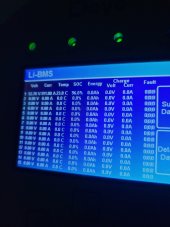
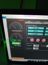
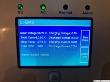
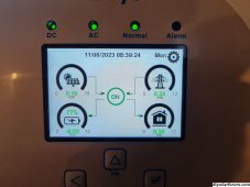
Sorry but which port you use exactly and which comm. method? It looks like you have partial communication. On the last picture, you can see what the inverter measures internally, but no other data which support the presence of BMS communication.Hi,
thank you.
This finally worked for me (I use the first RJ45 port on WNT board)
Now there are other problems.
Temperature reading is ok, but SOC not.
Bms SOC is different from Inverter SOC. So witch one is used for manage the inverter behaviour?
If I change BMS SOC from Daly PC software it change on BMS SOC side, but inverter still show old value.
Then if I disconnect RJ45 cable, inverter doesn't stop working, making system very unsafe.
Have you same issues?
Thank you all.
Wanted to share my updates here, so I contacted Daly and after sharing the details of my setup, they provided me with a Firmware for the WNT board, I did the upgrade on both WNT boards and all is working perfectly now.To allow Deye 5kw to communicate with Daly bms using protocol rs485 I did the below few steps:
1- On the deye inverter I set lithium mode to 12.
2- Using DalyBmsMonitor, under engineering model inverter set to Deye, protocol= RS485.
3- I used a straight RJ45 cable to connect my Daly WNT board, rs485 port to my Deye BMS rs485 port.
gfjardim
New Member
Hi, can you share the firmware or the support contact you used with Daly?Wanted to share my updates here, so I contacted Daly and after sharing the details of my setup, they provided me with a Firmware for the WNT board, I did the upgrade on both WNT boards and all is working perfectly now.
Hi, can you share the firmware or the support contact you used with Daly?
Hello, i recommed to contact Daly support,
but i''m sharing here the firmware and please do the update on your own repsonsibility
My BMS is 48v 16s 150amp LifePO4.
the support contact is
Attachments
Arnonijhof
New Member
- Joined
- Feb 28, 2020
- Messages
- 2
Hi, I think I understand what you did. I think I have a similar setup and I would like to ask you for a check of my conclusions:
Inverter: Deye sun-8k-sg04-lp3
Battery banks: 2x 16s with each its own daly SMARTBMS and 2 interface boards
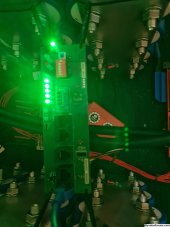
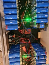
I connect each smartBMS to each interface board with the cable as provided by Daly and shown on the picture.
I connect the 2 interface boards with each other with a standard UTP cable (T568B wiring scheme) on the most right 8-pin port.
On interface board 1 I set dip switch 1 to ON (up)
On interface board 2 I set dip switch 2 to ON (up)
From interface board 1 I connect the LEFT RS485 port with a standard UTP cable (T568B wiring scheme) to the BMS port on the Deye inverter.
On the deye inverter I set lithium mode to 12.
Using DalyBmsMonitor, under engineering model inverter set to Deye, protocol= RS485.
Is this correct?
Thanks for your review of my setup. Much appreciated.
Inverter: Deye sun-8k-sg04-lp3
Battery banks: 2x 16s with each its own daly SMARTBMS and 2 interface boards
I connect each smartBMS to each interface board with the cable as provided by Daly and shown on the picture.
I connect the 2 interface boards with each other with a standard UTP cable (T568B wiring scheme) on the most right 8-pin port.
On interface board 1 I set dip switch 1 to ON (up)
On interface board 2 I set dip switch 2 to ON (up)
From interface board 1 I connect the LEFT RS485 port with a standard UTP cable (T568B wiring scheme) to the BMS port on the Deye inverter.
On the deye inverter I set lithium mode to 12.
Using DalyBmsMonitor, under engineering model inverter set to Deye, protocol= RS485.
Is this correct?
Thanks for your review of my setup. Much appreciated.
Attachments
Can you do a measurement of CAN/485 port at Daly side and tell me if you have any voltage anywhere ?hi.
had similar situation two days ago. and not even daly rep assistant could tell why Daly not communicating with deye through either CAN or rs485 port.
untill I interchanged can high and can low. (cross wired) it immediately communicated and could read all data.
all this was directly from daly CAN/rs485 port without any other accessories. But had ordered BMS with that requirement through Kevin Zhang on Alibaba
I have the connector but it is not labeled and have zero voltage all can/485 pins. Maybe there are no elements inside ?
UART is working so i think for someway UART to RS-485 if possible ?!
Hello, you have exactly the same setup i have.Hi, I think I understand what you did. I think I have a similar setup and I would like to ask you for a check of my conclusions:
Inverter: Deye sun-8k-sg04-lp3
Battery banks: 2x 16s with each its own daly SMARTBMS and 2 interface boards
I connect each smartBMS to each interface board with the cable as provided by Daly and shown on the picture.
I connect the 2 interface boards with each other with a standard UTP cable (T568B wiring scheme) on the most right 8-pin port.
On interface board 1 I set dip switch 1 to ON (up)
On interface board 2 I set dip switch 2 to ON (up)
From interface board 1 I connect the LEFT RS485 port with a standard UTP cable (T568B wiring scheme) to the BMS port on the Deye inverter.
On the deye inverter I set lithium mode to 12.
Using DalyBmsMonitor, under engineering model inverter set to Deye, protocol= RS485.
Is this correct?
Thanks for your review of my setup. Much appreciated.
shan198828
New Member
I have same problem with my deye 5kw and daly bms wnt board. I put straight utp cable both end and select 12 or 00 in deye but no respond
Attachments
Hi. First best regards from Slovenia and apologies for my English.
I own a Deye SUN-12K-SG04LP3-EU and made DIY battery pack with LTO batteries and two Daly BMSs connected to Daly interface board over RS485 (did tried also CAN but with same result..
I did not manage to get Deye working - he did received some data but not all and Error message was on screen with annoying alarm.
I tried different cable pinouts but without results.
So today I contacted Daly where I bought BMSs and got some information - see next post.
Attachments
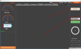
Daly send me a new firmware for interface board. You need cable RS485 to USB to connect to PC and you need DalyBmsMonitor software.
And in DalyBmsMonitor you need to choose WNT upgrade as shown in the picture - otherwise you wil brick your BMS.
After this update I reset BMS and interface board (unplug cables) and need again to set communication to RS485 and inverter Deye over DalyBmsMonitor on both BMSs. As explained in video on top of this side you need to set different address on interface boards and interconnect them with Ethernet cable.
Attachments
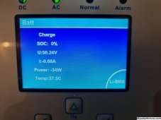
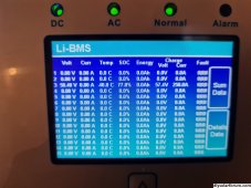
At the end I connected Deye with one board with a cable that has only first 3 pins connected on one side (see picture) and it works. Inverter is getting data that it needs. Only temperature is wrong as you can see from pic.
While connecting interface board for flashing you need to choose board address on top of DalyBmsMonitor software (BoardNo) - otherwise only board without address or with address 1 will show data.
Interestingly I can see only one BMS data - same as signo82 in his post - before there were two - not sure if this is OK.
Best regards,
Bogdan
Attachments
Similar threads
- Replies
- 4
- Views
- 102
- Replies
- 0
- Views
- 150
- Replies
- 1
- Views
- 459
- Replies
- 1
- Views
- 548