


You are using an out of date browser. It may not display this or other websites correctly.
You should upgrade or use an alternative browser.
You should upgrade or use an alternative browser.
Renogy DC DC Charger w/ MPPT
- Thread starter Will Prowse
- Start date
RandyP
Solar Enthusiast
- Joined
- Sep 21, 2019
- Messages
- 742
Can't fix my stupid too often. But I will try here. I was wrong, the ampacity of the one "-" wire from the the buss bar to the MCC50S "-" term point should be equal to the max solar panel "+" wire current plus the max Starter Battery "+" current plus the Battery Bank "+' current. That might be 3x9.85+75+65~180 amp wire. Could that be right ? Probably not, because the device only allows concurrent solar and start battery ampacity of 25A each for 50 amps total. The output to the Battery Bank is limited to 50A max. I think that the max ampacity of the one "-" wire should be 100 A. It might be a very short wire so perhaps voltage drop may not be significant (#6 AWG min wire size). I am using a #4 AWG wire for this. What do you think ?You might want to think about the current flowing in each ground cable, how it relates to where the cables are terminated. I think it is correct to use one 4AWG in the case you note above.
Last edited:
Group,......I was looking for my above post to edit it,.....and lo and behold,.....noticed that this very topic is being discussed just above my post,.....apologies for the redundant nature of the post,....and will now go read and learn. Brian in AustinWill, I plan on adopting your blueprint for the 400 watt plan with the above Renogy DC to DC controller and due to very limited roof space on my Sprinter RV, wanted to use 2 x 200 watt glass panels,....You previously had a recommended set of 200 watt glass panels, but they are no longer listed. Are there no acceptable 200 watt panels available in your opinion? Brian Collins Austin, TX (Village Farm Tiny Home community)
Lonesome Cowboy
New Member
- Joined
- Jul 2, 2020
- Messages
- 4
Want to buy one of the 100 amp MMPT, but they told me 6 weeks to deliver to Wyoming.
RandyP
Solar Enthusiast
- Joined
- Sep 21, 2019
- Messages
- 742
Who are "they" ?Want to buy one of the 100 amp MMPT, but they told me 6 weeks to deliver to Wyoming.
Is this the one, available at home depot webb order, pick up at your local home depot In Ft. Collins, July 10-15 ?
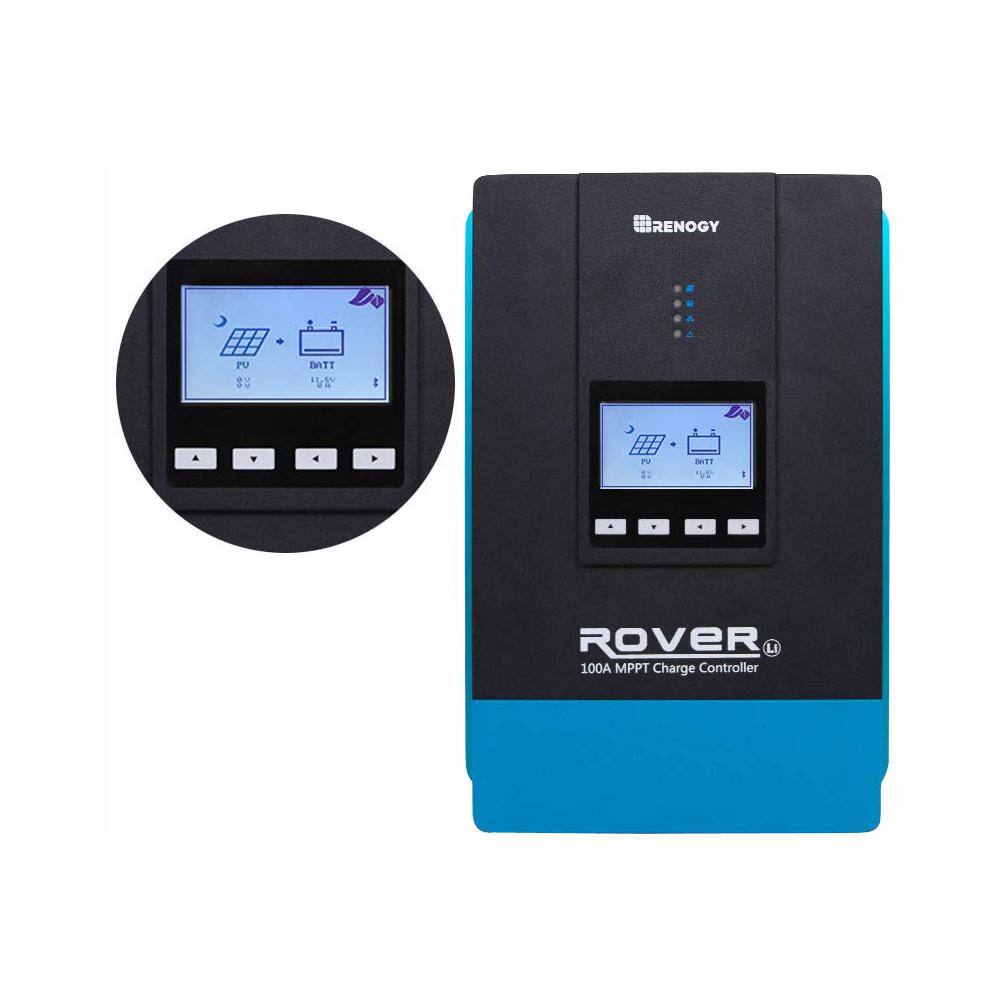
Renogy Rover Li 48-Volt 100 Amp MPPT Solar Charge Controller Auto LED Display RNG-CTRL-RVR100 - The Home Depot
Introducing the new 100 Amp Rover MPPT Charge Controller, the largest Rover controller that Renogy has to offer. Capable of supporting up to 1300-Watt on 12-Volt, 2600-Watt on 24-Volt, 3900-Watt on 36-Volt
www.homedepot.com
Last edited:
Safer is a subjective judgement.
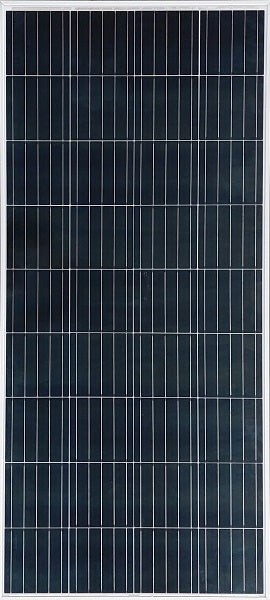
I am using HighTec Solar panels, rated at 210 w, they also have 200 W panels.
Hightec Solar 215W 36 Cell 12V Nominal Solar Panel - 5 Bus bar
Description HIGHTEC SOLAR 215W 36-cell 12V nominal solar panel is a photovoltaic module designed to convert sunlight into electrical energy. This Solar panel has a power rating of 215 watts. This indicates the maximum amount of power the panel can generate under ideal conditions, typically full...www.continuousresources.com
You might also check out NewPowa 200 W panel.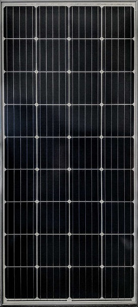
Hightec Solar 200W 36 Cell 12V Nominal Solar Panel - 5 Busbar - UL Listed
Description HIGHTEC SOLAR 200W 36-cell 12V nominal solar panel is a photovoltaic module designed to convert sunlight into electrical energy. This Solar panel has a power rating of 200 watts. This indicates the maximum amount of power the panel can generate under ideal conditions, typically full...
For safety, compare the panels ratings with the MCC50S specs. Stay within the MCC50S specs for safety.
200W 12V Monocrystalline Solar Panel
Newpowa 200W 12V Monocrystalline Solar Panel is commonly used in RV, marine, overlanding, traffic signals and various off-grid applications. Top experienced American solar panel brand. Free shipping!www.newpowa.com
Yes, run all the - circuits (as you itemized) to the - bus bar, then one negative from - BB to MCC50S controller. I suggested this before. It would be difficult to get three - circuit termlugs on the MCC50S - term point. I see that you have not added the three switch/CB's I suggested previoussly. You have not yet added a main fuse for the battery either.
Hey @RandyP thanks for your response.Yes, run all the - circuits (as you itemized) to the - bus bar, then one negative from - BB to MCC50S controller. I suggested this before. It would be difficult to get three - circuit termlugs on the MCC50S - term point. I see that you have not added the three switch/CB's I suggested previoussly. You have not yet added a main fuse for the battery either.
here's the updated diagram. You said I don't have a main fuse for the battery in there..? I have the 60A ANL fuse (circled in pink) - not sure where else you would be talking about?? Happy to replace that 60A ANL for an equivalent rated CB to ensue the DCC50S cab be easily isolated. I got a green square in place of where I'll put the CB off the + Solar panel as you've suggested. In your most recent message you mentioned "... the three switch/ CB's you mentioned earlier" - where do you think I need another CB?
Also, I order and received another Renogy 500A monitor (RBM500) incase the indication of "inversely connected terminals" was happen due to a defective bit of gear - I hooked the new RBM500 up today and sadly, with the starter batter connected and car running (charge being sent into the DCC50S) the backlight of the RBM immediately starts blinking again (which as per the RMB500 manual indicates B- and P- terminals are "inversely connected"
 ((
((
I'm using 4AWG everywhere.You might want to think about the current flowing in each ground cable, how it relates to where the cables are terminated. I think it is correct to use one 4AWG in the case you note above.
RandyP
Solar Enthusiast
- Joined
- Sep 21, 2019
- Messages
- 742
OK, here's the suggestions.Hey @RandyP thanks for your response.
here's the updated diagram. You said I don't have a main fuse for the battery in there..? I have the 60A ANL fuse (circled in pink) - not sure where else you would be talking about?? Happy to replace that 60A ANL for an equivalent rated CB to ensue the DCC50S cab be easily isolated. I got a green square in place of where I'll put the CB off the + Solar panel as you've suggested. In your most recent message you mentioned "... the three switch/ CB's you mentioned earlier" - where do you think I need another CB?
Also, I order and received another Renogy 500A monitor (RBM500) incase the indication of "inversely connected terminals" was happen due to a defective bit of gear - I hooked the new RBM500 up today and sadly, with the starter batter connected and car running (charge being sent into the DCC50S) the backlight of the RBM immediately starts blinking again (which as per the RMB500 manual indicates B- and P- terminals are "inversely connected"
View attachment 16775

?thanksOK, here's the suggestions.
View attachment 16810
RandyP
Solar Enthusiast
- Joined
- Sep 21, 2019
- Messages
- 742
Switching rated CB:
Main fuse at battery:
Starter Battery main switch.
Main fuse at battery:
Starter Battery main switch.
Last edited:
RandyP
Solar Enthusiast
- Joined
- Sep 21, 2019
- Messages
- 742
One more detail, put the chassis ground on the '-' bus, not the LiFePO4 battery '-' post. The shunt works better that way.OK, here's the suggestions.
View attachment 16810

Sgt Raven
Solar Addict
- Joined
- Feb 17, 2020
- Messages
- 1,079
I would use 4AWG as my minimum jumper, might step up to 2AWG. For your one short run, it shouldn't cast very much for that one.Can't fix my stupid too often. But I will try here. I was wrong, the ampacity of the one "-" wire from the the buss bar to the MCC50S "-" term point should be equal to the max solar panel "+" wire current plus the max Starter Battery "+" current plus the Battery Bank "+' current. That might be 3x9.85+75+65~180 amp wire. Could that be right ? Probably not, because the device only allows concurrent solar and start battery ampacity of 25A each for 50 amps total. The output to the Battery Bank is limited to 50A max. I think that the max ampacity of the one "-" wire should be 100 A. It might be a very short wire so perhaps voltage drop may not be significant (#6 AWG min wire size). I am using a #4 AWG wire for this. What do you think ?
Hi everyone, sorry for posting again. maybe the post got missed out.
i would like to seek some expertise from everyone here on how can i charge a solar generator using this DC-DC system that i intent to install in my vehicle.
generally i plan to have a small alternate lithium battery fixed in the vehicle to run some 12v items mainly LEDs(this battery will be permanently be in the vehicle)
but at the same time i would like to use a solar generator to provide all the 220v applications as a mobile inverter rather than a 12v-220v inverter so i can take it out to use anywhere when i need to.
i have did a edit from will diagram which i was thinking where can i tap the solar generator into from the wiring to charge it up.
i hope someone can help me with this.
thank you.
RandyP
Solar Enthusiast
- Joined
- Sep 21, 2019
- Messages
- 742
I used this tol :I would use 4AWG as my minimum jumper, might step up to 2AWG. For your one short run, it shouldn't cast very much for that one.
The #4 wire & lugs just fit in the 'slot' for wire & Terms in the MCC50S. Did the #2 wire also fit ?
RandyP
Solar Enthusiast
- Joined
- Sep 21, 2019
- Messages
- 742
From your post " solar generator to provide all the 220v applications as a mobile inverter ".Hi everyone, sorry for posting again. maybe the post got missed out.
i would like to seek some expertise from everyone here on how can i charge a solar generator using this DC-DC system that i intent to install in my vehicle.
generally i plan to have a small alternate lithium battery fixed in the vehicle to run some 12v items mainly LEDs(this battery will be permanently be in the vehicle)
but at the same time i would like to use a solar generator to provide all the 220v applications as a mobile inverter rather than a 12v-220v inverter so i can take it out to use anywhere when i need to.
i have did a edit from will diagram which i was thinking where can i tap the solar generator into from the wiring to charge it up.
i hope someone can help me with this.
thank you.
View attachment 16827
You must be in Europe.
Make/model/part number of solar generator ?
From your post " solar generator to provide all the 220v applications as a mobile inverter ".
You must be in Europe.
Make/model/part number of solar generator ?
Hi, i am from Singapore ??, we uses 220V here as well.
I am looking at either getting the ecoflow delta or bluetti AC200.
May i know you are asking for the model is it because different generator accept different charging voltage input thus placing the generator at different part of the diagram matters?
Sgt Raven
Solar Addict
- Joined
- Feb 17, 2020
- Messages
- 1,079
I don't understand the question. doesn't the DCC50S just use lugged cables for their hookups? I thought this thread was about the Renogy DCC50S.I used this tol :
The #4 wire & lugs just fit in the 'slot' for wire & Terms in the MCC50S. Did the #2 wire also fit ?
RandyP
Solar Enthusiast
- Joined
- Sep 21, 2019
- Messages
- 742
OOPs, DCC50S, not MCC50S. Yes, you are right.I don't understand the question. doesn't the DCC50S just use lugged cables for their hookups? I thought this thread was about the Renogy DCC50S.
The term points on the DCC50S just barely accepted my #4 wire (limited width channel) were you able to get #2 wire to fit ?
There are covers that go on the device and cover the wires. To use the covers the wire needs to fit in the slot.
I have interchanged MCC50S mistakenly for DCC50S in my last few posts. Sorry about this. I used the wrong term.
.jpg")

Last edited:
Similar threads
- Replies
- 16
- Views
- 534
- Replies
- 6
- Views
- 293
- Replies
- 1
- Views
- 590
- Replies
- 8
- Views
- 833
- Replies
- 11
- Views
- 326