diy solar

diy solar

JBD BMS, RS485 and Arduino

ladislavh

New Member
Joined
Jan 26, 2023
Messages
1
Location
Czech Republic
Hello,

Is there anyone who has working communication from JBD BMS via RS485 to Arduino?

I am using RS485-TTL conversion, but I am not able to get it working.

I found on the internet there is library to use UART, but I’d like to keep the bluetooth function as well. Maybe I will not avoid using that UART.

I’d be happy if anyone can share their solution, I need to display and work with data from BMS, it is not necessary needed via RS485, but as I said, I’d like to keep bluetooth as well, second option is manually disconnecting arduino from UART and inserting BT module temporarily.
 
I used this library - probably just the one you found though.


All I'd say is that it works very well. ?‍? I have added a triple-pole-double-throw switch to redirect the JBD's output to their USB adaptor for when I need to change parameters on the JBD/Overkill via a PC.
 
Hello,

Is there anyone who has working communication from JBD BMS via RS485 to Arduino?

I am using RS485-TTL conversion, but I am not able to get it working.

I found on the internet there is library to use UART, but I’d like to keep the bluetooth function as well. Maybe I will not avoid using that UART.

I’d be happy if anyone can share their solution, I need to display and work with data from BMS, it is not necessary needed via RS485, but as I said, I’d like to keep bluetooth as well, second option is manually disconnecting arduino from UART and inserting BT module temporarily.
What did you end up doing?
I would like to communicate with 5) JBD BMS 100 via RS485 ?
 
Hello All ,

Kindly , I have JBD BMS and also I need to communicate toit by arduino and display the voltage , current and capacity . I used the library in the below link JdbBms.h and the code ( basic.ino ) but I didnt get anything on the serial monitor . I connected the JBD BMS ( gnd , tx & rx ) to the arduino pin ( 6 & 7 ) as the code , Could please anyone help

link : https://github.com/rakhmaevao/JbdBms

code ( basic )

#include "JbdBms.h"

JbdBms myBms(6, 7); // RX, TX

void setup()
{
Serial.begin(9600);
Serial.println("JBD bms driver");
}

void loop()
{
if (myBms.readBmsData() == true)
{
Serial.print("This capacity: ");
Serial.println(myBms.getChargePercentage());
Serial.print("This current: ");
Serial.println(myBms.getCurrent());
Serial.print("Protection state: ");
Serial.println(myBms.getProtectionState());
Serial.println();
}
else
{
Serial.println("Communication error");
}
delay(1000);
}

 
The library I posted earlier in this thread works well ;)
 
Hello SeaGal , does the library you posted work with Jbd bms ? Does the arduino connected to uart port.? , thanks .
Best regards
 
I See that its for overkill bms , but if you tried it and ut worked , then its ok . Thanks
 
I have made this work with UART and TFT display with Arduino nano every.


I m also looking to make arduino work with rs485 as UART is used by bluetooth and I want to retain the capability to check via phone app as well. any leads would be helpful.
 
Hello SeaGal , does the library you posted work with Jbd bms ? Does the arduino connected to uart port.? , thanks .
I have an Overkill badged JBD. It works with my Overkill one. I suspect that are no differences with the UART comms though, because the Chinese original JBD Windows application works fine with the Overkill badged JBD.
 
I have an Overkill badged JBD. It works with my Overkill one. I suspect that are no differences with the UART comms though, because the Chinese original JBD Windows application works fine with the Overkill badged JBD.
Hey SeaGal,

Did you use RS485/TTL to arduino and made this work with JBD BMS?

I am trying to do that but I cannot for god's sake get any value..


EDIT: Ah nevermind, I finally was able to execute it. It seems we had to uncomment few lines in the cpp files or move over some functions to the examples. If anyone else is having issues in future, here is the a simple example of what I am doing.

@ladislavh

SOLUTION

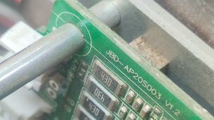
I am using 20S003 (old 300A JBD BMS) with UART&RS485 marked in the BMS. If you do not have RS485 marked in the BMS, it won't work (plus they wont have the RS485 connector even if they are labels in the board). Its marked A/H and B/L in the board and its the RS485 connector.

IMG_20240310_112708.jpg

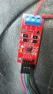
Then, I connected these 2 pins to RS485 TTL converter. A to A and B to B.

IMG_20240314_134547.jpg

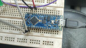
I am using Arduino Nano Every so it works in 5V thus I connected them directly (maybe resistors might be better).


TXD goes to RX (pin 1)
RXD goes to TX (pin 0)
VCC goes to VCC of arduino (+5v)
GND goes to GND of arduino

IMG_20240314_134609.jpg

Then, I moved this library to Arduino Libraries: https://github.com/FurTrader/Overkill-Solar-BMS_2-Arduino-Library

I opened up an example and tweaked the code to this to get to see if I can get the current varying quickly:


C:
    #include "bms2.h"

    OverkillSolarBms2 bms = OverkillSolarBms2();

    void setup() {

        Serial.begin(115200);
        Serial1.begin(9600);

        bms.begin(&Serial1);
        Serial.println("JBD BMS:");

    }

    void loop() {
        while(1) {
            bms.main_task(true);
            if (millis() >= 1000) {
                break;
            }
            delay(10);
        }

        Serial.println("==========================");
        Serial.print("Current:           ");
        Serial.print(bms.get_current(), 3);
        Serial.println("A");

    }


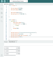
Its showing the current quickly..

Screenshot 2024-03-14 at 1.52.31 PM.png

Next step is to show all the needed data to a TFT display! YaY!!
 
Last edited:
Did you use RS485/TTL to arduino and made this work with JBD BMS?
FYI; my Overkill JBD only had TTL UART interface on it; there is no RS485 port on my BMS. I used the read/write version of the Overkill arduino library (as linked above) to get the data into an ESP32 using its serial port with a 5v to 3.3v resistor divider for the ESP's RX data.

Then, the ESP32 is connected to an MCP2515-based module with CANBus transceiver to connect to my Solis inverter.

EDIT: Ah nevermind, I finally was able to execute it.
(y)
 
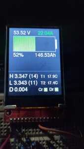
I was able to move the UART codes to RS485 connector to display in the TFT display as well. This will soon be in my small ev rebuild project, will also add few other features. After so many days! :) I wanted to use RS485 because UART is used by bluetooth module and I want to use the app for more details or set things while this screen will be handy for driving. And yes, I could have just used the default screen but it was too big and it didn't show the necessary parameters that I needed. Plus, I can now use this screen for other car functionalities too.

IMG_20240314_204841.jpg
 
Last edited:
Hey SeaGal,

Did you use RS485/TTL to arduino and made this work with JBD BMS?

I am trying to do that but I cannot for god's sake get any value..


EDIT: Ah nevermind, I finally was able to execute it. It seems we had to uncomment few lines in the cpp files or move over some functions to the examples. If anyone else is having issues in future, here is the a simple example of what I am doing.

@ladislavh

SOLUTION

I am using 20S003 (old 300A JBD BMS) with UART&RS485 marked in the BMS. If you do not have RS485 marked in the BMS, it won't work (plus they wont have the RS485 connector even if they are labels in the board). Its marked A/H and B/L in the board and its the RS485 connector.

View attachment 202022

Then, I connected these 2 pins to RS485 TTL converter. A to A and B to B.

View attachment 202023

I am using Arduino Nano Every so it works in 5V thus I connected them directly (maybe resistors might be better).


TXD goes to RX (pin 1)
RXD goes to TX (pin 0)
VCC goes to VCC of arduino (+5v)
GND goes to GND of arduino

View attachment 202024

Then, I moved this library to Arduino Libraries: https://github.com/FurTrader/Overkill-Solar-BMS_2-Arduino-Library

I opened up an example and tweaked the code to this to get to see if I can get the current varying quickly:


C:
    #include "bms2.h"

    OverkillSolarBms2 bms = OverkillSolarBms2();

    void setup() {

        Serial.begin(115200);
        Serial1.begin(9600);

        bms.begin(&Serial1);
        Serial.println("JBD BMS:");

    }

    void loop() {
        while(1) {
            bms.main_task(true);
            if (millis() >= 1000) {
                break;
            }
            delay(10);
        }

        Serial.println("==========================");
        Serial.print("Current:           ");
        Serial.print(bms.get_current(), 3);
        Serial.println("A");

    }


Its showing the current quickly..

View attachment 202025

Next step is to show all the needed data to a TFT display! YaY!!
Hey, can you tell which lines you have uncommented i can't seem to get the data no matter what.
 
Back
Top