diy solar

diy solar

how to hook up shunt meter

SunbeltLocked

If I'm not under arrest, I should be free to go?
Joined
Mar 21, 2022
Messages
29
Location
Wyoming
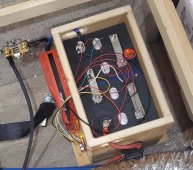
I have a DC shunt meter which (the shunt) needs to be hooked up at the DC power (labeled A) and the DC load (labeled B). I just need to know which side of the battery to charge controller (positive or negative) to place the shunt, or does it make any difference?
DC shunt meter.jpg
Shunt Position.jpg
 
DC 6.5V - 100V is the battery (on the left in the diagram). The diagram clearly shows it connected to the black negative side. Check out the diagram in post #1.
 
Editied for clarity
The shunt in the instruction sheet appears to be a 'dumb' shunt. (No built in circuitry). Therefor the direction of the shunt itself does not matter. However, make sure the wires shown as blue and orange are on the battery side of the shunt and the green is on the load side of the shunt.

However, All loads and chargers should be 'after' the shunt on the negative side.

1650586909383.png
 
As the diagram shows shunt goes on the negative lead and goes to chassis ground or negative bus bar. In the picture My shunt is mounted on the wall then goes to the negative bus bar.
 

Attachments

  • 20220320_182748.jpg
    20220320_182748.jpg
    461.6 KB · Views: 7
As the diagram shows shunt goes on the negative lead and goes to chassis ground or negative bus bar. In the picture My shunt is mounted on the wall then goes to the negative bus bar.
Yes. Good point. The BMS is part of the battery. The BMS will be on the negative line between the cells and the shunt.

Note: The electrodacus BMS is a one-off type of BMS and it's associated Shunts are on the positive side. This is the only time I have seen the shunt on the positive side of the circuit.
 
OK then it's a good thing I asked because I would have thought the charge controller is the power and the battery is the load since the cc is charging the battery.
 
OK then it's a good thing I asked because I would have thought the charge controller is the power and the battery is the load since the cc is charging the battery.
During the battery charging phase the CC is the power source, and when the CCis not charging then the battery is the power source, so based on the diagram, the meter will show the power draw from the battery, but during charging mode the meter may show negative number if it is designed to show for the current flow in both directions, I.E. showing + xxxA duribg charging, and - xxxA during discharging.
 
So then since I have 2 of these shunt meters, I could put the other one between the inverter and battery with the... (now I'm really confused).
 
lets back up and talk about how a battery monitor works. The following was done for the Aili monitor, but it will be basically the same for all of them.
1650595700929.png

Notice that the monitor sees both negative and positive voltages depending on the direction of the current. Therefor it knows the difference between current going into the battery and out of the battery. That is how it keeps track of the total charge in the battery.

I have not played with the monitor you have, but I am confident it operates on the same principles. You only need one shunt, on the negative side of the battery and between the battery/BMS and all loads or chargers.
 
Suppose I wanted to measure current coming from the wind generator, (I already have a shunt on the negative side to measure use), how would one wire that? Would it be the same as wiring on the negative side except reversing negative black for red positive?
 
Back
Top