ScrotpusGobbleBottom
Corn Pop was a bad dude.
If you can, yes.just turn on as needed?


If you can, yes.just turn on as needed?
| Brand | Renogy |
| Voltage | 24 Volts |
Just buy one more solar panel like the one you have. You will probably want more power in the future and this idea would help. 2, 21v VOC panels in series would be plenty of voltage for a 24v setupOk, so that I understand, I can either keep what I have and get a 12v inverter or upgrade my solar panel to one that has at least 40v charging output ? I am also concerned that I might have bought a controller that is too small.
Brand Renogy Voltage 24 Volts
Ok, so that I understand, I can either keep what I have and get a 12v inverter or upgrade my solar panel to one that has at least 40v charging output ? I am also concerned that I might have bought a controller that is too small.
Brand Renogy Voltage 24 Volts
Thank you. I am now kicking myself for returning the other one! So is there a special plug to bridge the two together? Not sure that both terminals will fit in controller ports. They are pretty small holes.Just buy one more solar panel like the one you have. You will probably want more power in the future and this idea would help. 2, 24v panels in series would be plenty of voltage for a 24v setup
You would never have any doubled up connections with a series panel setup. Look up how that is wired. One of the panels neg would be going to the other panels POS. You could probably do this with the existing MC4 connector on the panels.Thank you. I am now kicking myself for returning the other one! So is there a special plug to bridge the two together? Not sure that both terminals will fit in controller ports. They are pretty small holes.
Thank you. I am now kicking myself for returning the other one! So is there a special plug to bridge the two together? Not sure that both terminals will fit in controller ports. They are pretty small holes.
I was a little confused with this as they both have a positive and a negative plug. I guess the 1st panel negative stays unplugged?You would never have any doubled up connections with a series panel setup. Look up how that is wired. One of the panels neg would be going to the other panels POS. You could probably do this with the existing MC4 connector on the panels.
Still not completely sure on how to connect the 2 batteries together and where the controller terminals go. I have the cable from the positive inverter terminal going to the 2nd battery positive, bridged the negative from the 1st battery to the 2nd battery positive, then the negative from the 2nd battery to the converter negative. The controller is connected to just the 1st battery's + & - , which I understand is incorrect? But when I try putting the positive of the controller to the unbridged positive of the 2nd battery and the same to the unbridged necative of the 1st battery the controller battery icon flashes as if it is incorrectly connected.

Now it seems that it will be better just to change the inverter to a 12v and just keep everything else since the only continuous item I will be using is the bug zapper. Thank you everyone for helping a noobie out!
I was a little confused with this as they both have a positive and a negative plug. I guess the 1st panel negative stays unplugged?

Still not completely sure on how to connect the 2 batteries togeth
No, first panel negative to charge controller, first panel positive to negative of second panel, positive of second panel to charge controller.I was a little confused with this as they both have a positive and a negative plug. I guess the 1st panel negative stays unplugged?
Could be that it is incorrectly connected with polarity reversed. Or it might be that the voltage from the batteries in series is too low because you only charged one while draining from two. Follow the advice to individually charge each battery. You can even do this with your present setup from the SCC. if wired to one battery at a time over the next few days (no other thing wired to the battery!!) make sure your SCC is set properly for lithium batteries.Still not completely sure on how to connect the 2 batteries together and where the controller terminals go. I have the cable from the positive inverter terminal going to the 2nd battery positive, bridged the negative from the 1st battery to the 2nd battery positive, then the negative from the 2nd battery to the converter negative. The controller is connected to just the 1st battery's + & - , which I understand is incorrect? But when I try putting the positive of the controller to the unbridged positive of the 2nd battery and the same to the unbridged necative of the 1st battery the controller battery icon flashes as if it is incorrectly connected.
This is what I think may have happened.charged one while draining from two

They are only 50ah eachNow I guess I will buy the 2nd solar panel and bridge it together to complete the system. I hope tge batteries aren't too small to store the power
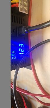
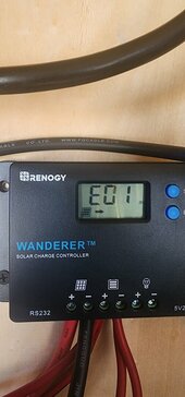
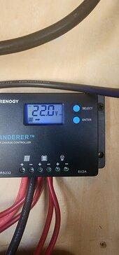
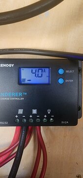
You NEED to make sure the batteries are the same or very similar voltage before you charge them.Thank you so much guys for all the feedback. So after reviewing all the threads on here, the culprit was the controller. The settings were off. I changed the volts to 24 and the battery setting to lithium and the flashing on the controller went away. Now the indicator is showing low charge on battery which would be correct since it was not wired correctly. I guess now I can see how long it would take for both batteries to get a full charge. Here are the readings after the correction...
They are fine. you have about 1200 watt hours, You could mostly charge that (80%) on a good sunny day with 2 100 watt panels.I hope tge batteries aren't too small to store the power
They are both the same size and typeYou NEED to make sure the batteries are the same or very similar voltage before you charge them.
You got 22v which is a good sign. Do you have a multi-meter?
VOLTAGE .. size and type has nothing to do with current voltage or general health.They are both the same size and type