diy solar

diy solar

JK-BMS-CAN with new Cut-Off Charging Logic (open-source)

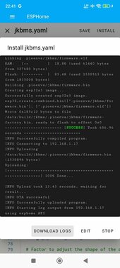
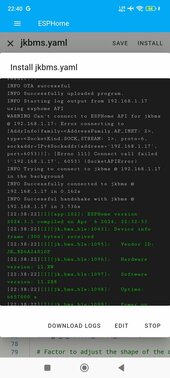
OTA Version 2 also just failed ...
I just opened a GitHub Issue on the ESPHome Issue Tracker:

I do NOT have high hopes that it will be resolved quickly though.

I'll try to see if I can get any of the custom web server libraries (several are available on GitHub that work with esp-idf framework without needing the Arduino one) that support OTA (and possibly also HTTPS).

I might also wonder if this is a low-RAM issue, since the Atom S3 Lite does NOT have integrated/external PSRAM (typically 2-8 MB) but only 320 kB usable (although should be 520 kB total according to Wikipedia).

Is anybody here using the Atom S3 Lite WITH OTA working correctly ? Or are those who managed to get OTA working using ESP32/ESP32-S3 MODULES which have far more (PS)RAM and Potentially Flash ?

If I recall correctly also @chaosnature had issues with OTA on the Atom S3 Lite ...

Not sure if it's a requirement also to set up a custom Partition Layout for ESPHome to handle OTA correctly ...
 
I might also wonder if this is a low-RAM issue, since the Atom S3 Lite does NOT have integrated/external PSRAM (typically 2-8 MB) but only 320 kB usable (although should be 520 kB total according to Wikipedia).
I have the cheapest ESP32 Dev boards and even they handle OTA perfectly fine.
This is not the issue.

This is the output on my windows PowerShell.

Code:
CONFIGURATION: https://docs.platformio.org/page/boards/espressif32/esp32doit-devkit-v1.html
PLATFORM: Espressif 32 (5.4.0) > DOIT ESP32 DEVKIT V1
HARDWARE: ESP32 240MHz, 320KB RAM, 4MB Flash
DEBUG: Current (cmsis-dap) External (cmsis-dap, esp-bridge, esp-prog, iot-bus-jtag, jlink, minimodule, olimex-arm-usb-ocd, olimex-arm-usb-ocd-h, olimex-arm-usb-tiny-h, olimex-jtag-tiny, tumpa)

it even shows estimates for RAM and FLASH consumption for the compiled binary.

Code:
Compiling .pioenvs\shvm-jk\src\main.o
Linking .pioenvs\shvm-jk\firmware.elf
Retrieving maximum program size .pioenvs\shvm-jk\firmware.elf
Checking size .pioenvs\shvm-jk\firmware.elf
Advanced Memory Usage is available via "PlatformIO Home > Project Inspect"
RAM:   [==        ]  17.6% (used 57548 bytes from 327680 bytes)
Flash: [========  ]  75.8% (used 1390949 bytes from 1835008 bytes)
Building .pioenvs\shvm-jk\firmware.bin
esptool.py v4.4
Creating esp32 image...
Merged 26 ELF sections
Successfully created esp32 image.
esp32_create_combined_bin([".pioenvs\shvm-jk\firmware.bin"], [".pioenvs\shvm-jk\firmware.elf"])
esptool.py v4.7.0
Wrote 0x165200 bytes to file D:\Desktop\JKcan\.esphome\build\shvm-jk\.pioenvs\shvm-jk/firmware-factory.bin, ready to flash to offset 0x0
I ran out of Atom S3 Lite and will need to order some extra to try to replicate.

In the meantime I'll try another ESP32-S3 dev board (module this time) on a Raspberry Pi using dnsmasq + hostapd with the same Alfa AWUS1900 USB-Wifi Adapter (RTL8814AU) in AP mode.

It might be that the whole ESP32-S3 (note the "S3" part) is not working, but the "standard" ESP32 is working fine.
 
This is what happens with an ESP32-S3 module.
Not sure if I have been scammed on Aliexpress ?

I am getting panics all over the place ...
 

Attachments

  • esp32-s3_module_usb_flashing.txt
    49.5 KB · Views: 8
Is the ATOM Lite ESP32 still compatible? Thinking of reflashing the most current version and trying it out again with my EG4 6000xp.
 
Is the ATOM Lite ESP32 still compatible? Thinking of reflashing the most current version and trying it out again with my EG4 6000xp.
Do you mean the ESP32 or ESP32 S3 ?


vs


Maybe the only option is to have all of these devices PERMANENTLY connected to a USB hub and a Raspberry or something.

That way if you need to flash you can do it through a "proxy" :rolleyes: .
 
I run several esp32s2lolin and have no problem with OTA until now:
OTA:
- port: 8266

Instead of using dhcp, I set manual Ip or bind ip to mac at router so the esp32 will always have fix address.
I used 'use_address: ip_address_of_mydevice
>> all working fine.
I run tens of esp32lolin in ten remote areas with NAT set up for port 8266 in remote site. Sometime i have more device, i used different OTA ports. Remote device use mqtt for updating information to my HA server.
In most of the case I believe the resolving of device ip address have problem, so better make it fix!
I have no problems resolving or pinging the device. The problem must be elsewhere ...
 
Do you mean the ESP32 or ESP32 S3 ?


vs


Maybe the only option is to have all of these devices PERMANENTLY connected to a USB hub and a Raspberry or something.

That way if you need to flash you can do it through a "proxy" :rolleyes: .
I have Atom Lite (not S). Also I only flash with USB. So is there a problem with the non-S version?
 
Well V1.16.4 works fine on it. Safe to assume 1.17.x will?
If you flash via USB only, I don't think there is something to worry about :) . Not regards to flashing process at least.

The automatic charge voltage control still needs some tuning IMHO.

I am testing @MrPablo updated branch of automatic voltage control and to be honest I do NOT remember how it behaved on "RAW" 1.17.5.
lol. Maybe I’ll wait
 
There's no reason you can't test out v1.17.5 and disable Auto Voltage Control, it will still send static voltages appropriate to each charging stage.
 
No 11.43 will not response to request data command as I have mentioned (my version 11.36, 11.42 does not work on wired connection anymore, the "4E:57:00:13:00:00:00:00:06:02:00:00:00:00:00:00:68:00:00:01:28" command does not work! I have not upgraded to V15 as guided by JK-BMS guy as I have not seen any guidance on that and not sure the V15 is supported the upgrading from V11. The only way that seems possible is to use Bluetooth for multiple BMS (my previous pose has the link but I have not tried yet)

@RostadKatt

All I can tell you is that the wired version works with this version:

JKB2A20S20P (heat + can) HW: V11.XW and SW: V11.285H.

What we are saying @paulsteigel is worrying... to my knowledge it is not possible to upgrade the JK-BMS (except the new JK-BMS inverter model).
 
Last edited:
1.: Thanks @Sleeper85, Actually, I used this approach for both ends but using 98 and the minimum SOC (not 2%) to reflect the SOC cut-off level needed for the Inverter to stop charging (.i.e Cut-off/ On-grid EOD set at 20% but JK SOC is lower when minimum cell voltage is still 3.1V or more, the SOC reporting to Inverter shall be kept at 21% till min cell voltage goes below 3.2 or 3.1 depending on user's prefer cut off voltage level). If I dont change the SOC at the EOD SOC, inverter will stop discharging when cell voltage is still high enough.
So the SOC changes is only at ends not during the charge/discharge process!
2.: MultiBMS: I have 2 battery (one with JK-BMS and one with Huawei brand (different BMS from Huawei). I wired them in parallel and have just an additional slider for defining the capacity of the battery in parallel. This will help regulating the total charging current limit sent to the Inverter. It would be better if we can monitor current at other battery but I found that my Lux inverter does have internal shunt for both voltage and current so I don't need to make it become more complicated. Principally, we can do wire connection (also require to keep the JST interface be longer) to several BMS using Software serial but the returning value is not much (only data about cell, alarm) while what we need is to control charge/discharge well enough. My recent observation is: new JKBMS Soft Version 11.36 and higher (11.XW) does not allow UART command query anymore (image from JKBMS technical staff).
View attachment 206862View attachment 206864
They recommended to upgrade to V15 but does not share further information at all.
Many thanks for your sharing!

@chaosnature

If I remember correctly you never managed to get the wire version to work?

what is the hardware and firmware version of your BMS?
 
Also, I'd like to add my two cents to this amazing project.

I've prepared a summary connection diagram for those who are going to use the M5Stack—a nice product that simplifies the wiring and connections, making the hardware part almost plug and play.
Both configurations have been tested and are stable

View attachment 198115
I tried connecting the JKBMS to the PIP-5048GEW via CAN Bus but it didn't work.
After about 2 minutes there was an error code 61 on the PIP-5048GE.
My device:
- Inverter MPPSolar PIP-5048GEW
- JKBMS JK-BD6A24S10P HW: 11.XW SW: 11.288
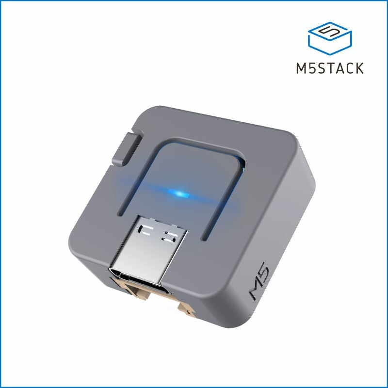
- ESP32 AtomS3 Lite
- CAN bus transceiver ATOMIC CANBus Base (CA-IS3050G)

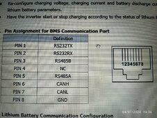
Does anyone know the CAN BUS pinout of PIP-5048GEW.
Thank you in advance.

1000275224.jpg1000275025.jpg1000275098.jpg1000275097.jpg
 
Last edited:
I tried connecting the JKBMS to the PIP-5048GEW via CAN Bus but it didn't work.
After about 2 minutes there was an error code 61 on the PIP-5048GE.
My device:
- Inverter MPPSolar PIP-5048GEW
- JKBMS JK-BD6A24S10P HW: 11.XW SW: 11.288
- ESP32 AtomS3 Lite
- CAN bus transceiver ATOMIC CANBus Base (CA-IS3050G)

Does anyone know the CAN BUS pinout of PIP-5048GEW.
Thank you in advance.

View attachment 207615View attachment 207616View attachment 207617View attachment 207618
- Please CONFIRM the SKU part number of the M5Stack Controller (Atom S3 Lite) and especially the CANbus Isolated Adapter (one is UNIT the other is BASE). I was using the wrong one (UNIT/Base confusion, availability at suppliers, ...) so the GPIO pinout was wrong.

- Did you try reversing CAN_TX and CAN_RX ? Did you try reversing the GPIO pins on the ESP32 side in the config ?

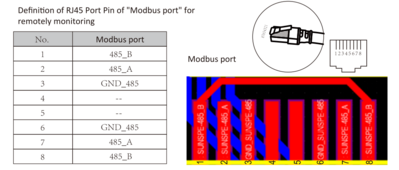
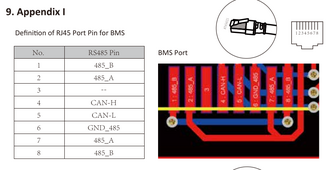
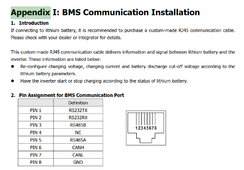
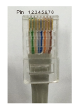
- Did you try pin 2+3 or 6+7 ? Depending on how you look at the RJ45 Plug (from front or from back ? with "locking tab" facing up or down ? etc) or RJ45 Socket (from front or from back ? with space for the "locking tab" facing up or down ? etc) it can be different. And of course there are plenty of "opportunities" to switch everything around. I was VERY methodical for the RS485 Inverter Communication (NOT the CANbus where I got the pinout wrong ...), but it's VERY easy to get it backwards ...

This is for my Deye Modbus Port:
1712479942740.png

While the BMS (the one you are trying to use) is:

1712479993422.png

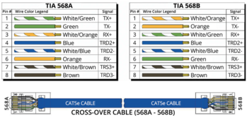
- Are you sure you are NOT making a Crossover cable by mixing TIA 568A and TIA 568B ?
1712480053134.png

- Did you add the Termination Resistor (120 Ohm) ?

- To check the basic communication if you are on GNU/Linux with some CANbus adapter lying around you could try "cansniff" command part of the "can-utils" package.

That's what I tried here: https://diysolarforum.com/threads/j...-logic-open-source.79325/page-37#post-1046211

EDIT 1: on your inverter I can see this at https://www.mppsolar.com/manual/PIP-GEW/3024_5048GEW manual-20230919.pdf
1712480609364.png

So the proper pins if you look at the RJ45 Plug with the locking tab facing DOWN (!!) are the pins on the RIGHT side.
Look at my Deye screenshot for more information (you need to turn the RJ45 Plug 180° to match the RJ45 socket, then the Pin 7+8 of the RJ45 Plug are on the right side [when the RJ45 locking tab is facing DOWN], just like the RJ45 Socket).
 
Last edited:
I tried connecting the JKBMS to the PIP-5048GEW via CAN Bus but it didn't work.
After about 2 minutes there was an error code 61 on the PIP-5048GE.
My device:
- Inverter MPPSolar PIP-5048GEW
- JKBMS JK-BD6A24S10P HW: 11.XW SW: 11.288
- ESP32 AtomS3 Lite
- CAN bus transceiver ATOMIC CANBus Base (CA-IS3050G)

Does anyone know the CAN BUS pinout of PIP-5048GEW.
Thank you in advance.

View attachment 207615View attachment 207616View attachment 207617View attachment 207618
According to the diagram you have attached, pin 6 is CANH and pin 7 is CANL. The picture is contacts side facing up towards the viewer.
these two wires should be connected to the module's CANH and CANL output pins respectively.
Also, I'm assuming you've already set the Inverter to the appropriate PYLONTECH battery mode.
1712481213288.png
 
Last edited:
I tried connecting the JKBMS to the PIP-5048GEW via CAN Bus but it didn't work.
After about 2 minutes there was an error code 61 on the PIP-5048GE.
My device:
- Inverter MPPSolar PIP-5048GEW
- JKBMS JK-BD6A24S10P HW: 11.XW SW: 11.288
- ESP32 AtomS3 Lite
- CAN bus transceiver ATOMIC CANBus Base (CA-IS3050G)

Does anyone know the CAN BUS pinout of PIP-5048GEW.
Thank you in advance.

View attachment 207615View attachment 207616View attachment 207617View attachment 207618

You can always try but according to my readings the PYLON protocol on Voltronic inverters like MPP Solar only works on RS485 and not on CAN bus. On the other hand, the can bus should work for two other battery models with a protocol completely different from what we use (therefore not supported).
 
@chaosnature

If I remember correctly you never managed to get the wire version to work?

what is the hardware and firmware version of your BMS?
Good memory,

Correct - Wire never worked for my , Tried GPIO1 and 3/ also the default 16/17...but no joy on any of the Code versions...(not tried it on the .17.x versions tho)
mine is JK2a24s15p

i just decided to stick with BLE instead...i know the risk , but its doing the job so far.
 
For those having issues with OTA failing to upload, like at 4% - 10% or so, the FIRST thing to check if your network connectivity, configuration, routing, firewall, etc.

I lost 2 days trying to sort out why OTA would fail, the watchdog getting triggered, then the device BRICKS without even resetting itself.

In some cases cycling USB Power Supply is enough to make it recover. But in some/most cases, you need to USB flash AGAIN.

The network connectivity seems fine, although if you ping long enough you can see the latency increasing dramatically.

But there is NOT really a network "failure" per se ...

Code:
root@MYHOSTNAME:~# ping -c 20 esp32-s3-base.local
PING esp32-s3-base.local (172.27.30.1) 56(84) bytes of data.
64 bytes from esp32-s3-base.local (172.27.30.1): icmp_seq=1 ttl=254 time=87.4 ms
64 bytes from esp32-s3-base.local (172.27.30.1): icmp_seq=2 ttl=254 time=8.65 ms
64 bytes from esp32-s3-base.local (172.27.30.1): icmp_seq=3 ttl=254 time=31.1 ms
64 bytes from esp32-s3-base.local (172.27.30.1): icmp_seq=4 ttl=254 time=55.2 ms
64 bytes from esp32-s3-base.local (172.27.30.1): icmp_seq=5 ttl=254 time=86.5 ms
64 bytes from esp32-s3-base.local (172.27.30.1): icmp_seq=6 ttl=254 time=102 ms
64 bytes from esp32-s3-base.local (172.27.30.1): icmp_seq=7 ttl=254 time=30.7 ms
64 bytes from esp32-s3-base.local (172.27.30.1): icmp_seq=8 ttl=254 time=53.6 ms
64 bytes from esp32-s3-base.local (172.27.30.1): icmp_seq=9 ttl=254 time=77.2 ms
64 bytes from esp32-s3-base.local (172.27.30.1): icmp_seq=10 ttl=254 time=102 ms
64 bytes from esp32-s3-base.local (172.27.30.1): icmp_seq=11 ttl=254 time=25.2 ms
64 bytes from esp32-s3-base.local (172.27.30.1): icmp_seq=12 ttl=254 time=45.5 ms
64 bytes from esp32-s3-base.local (172.27.30.1): icmp_seq=13 ttl=254 time=1810 ms
64 bytes from esp32-s3-base.local (172.27.30.1): icmp_seq=14 ttl=254 time=787 ms
64 bytes from esp32-s3-base.local (172.27.30.1): icmp_seq=15 ttl=254 time=296 ms
64 bytes from esp32-s3-base.local (172.27.30.1): icmp_seq=16 ttl=254 time=421 ms
64 bytes from esp32-s3-base.local (172.27.30.1): icmp_seq=17 ttl=254 time=750 ms
64 bytes from esp32-s3-base.local (172.27.30.1): icmp_seq=18 ttl=254 time=466 ms
64 bytes from esp32-s3-base.local (172.27.30.1): icmp_seq=19 ttl=254 time=285 ms
64 bytes from esp32-s3-base.local (172.27.30.1): icmp_seq=20 ttl=254 time=102 ms

--- esp32-s3-base.local ping statistics ---
20 packets transmitted, 20 received, 0% packet loss, time 19036ms
rtt min/avg/max/mdev = 8.649/281.088/1809.820/418.520 ms, pipe 2
root@MYHOSTNAME:~# traceroute esp32-s3-base.local
traceroute to esp32-s3-base.local (172.27.30.1), 30 hops max, 60 byte packets
 1  192.168.1.7 (192.168.1.7)  0.513 ms  0.431 ms  0.436 ms
 2  192.168.4.31 (192.168.4.31)  0.825 ms  0.884 ms  0.989 ms
 3  esp32-s3-base.local (172.27.30.1)  62.587 ms  66.768 ms  66.756 ms
root@MYHOSTNAME:~# tcptraceroute esp32-s3-base.local
Running:
    traceroute -T -O info esp32-s3-base.local
traceroute to esp32-s3-base.local (172.27.30.1), 30 hops max, 60 byte packets
 1  192.168.1.7 (192.168.1.7)  0.450 ms  0.450 ms  0.399 ms
 2  192.168.4.31 (192.168.4.31)  1.086 ms  0.880 ms  0.734 ms
 3  esp32-s3-base.local (172.27.30.1) <rst,ack>  53.865 ms  58.118 ms  61.274 ms

Out of desperation, I tried to flash the firmware from the Raspberry Pi that is running the AP, so it's DIRECTLY in the correct subnet for the esp32 device that it's trying to flash. Upload the firmware on the Raspberry Pi server first, you do NOT want to wait for all the time it takes for it to compile (Raspberry Pi 2 here ...):
Bash:
#!/bin/bash

# Activate Python venv
source ~/ESPHome/venv/bin/activate

# Flash Device
esphome upload esp32-s3-base.yaml --file firmware.bin --device esp32-s3-base.local

Root cause was to enable (on the Rock 5B in the Garage or the Raspberry Pi that I have in the House for some warmer-environment testing) in /etc/sysctl.conf (for Debian/Raspberry Pi OS/Ubuntu and similar GNU/Linux Distributions):
Code:
net.ipv4.ip_forward=1

That's probably causing some serious flooding of the different subnets which are now "merged" into one, without NAT/Masquerading or other stuff to take care of these conflicts.

In past versions this was done by iptables, but nowadays it got replaced by nftables, which is very different to configure.

That's what I need to figure out right now ....
 
Last edited:

diy solar

diy solar
Back
Top