diy solar

diy solar

JK-BMS-CAN with new Cut-Off Charging Logic (open-source)

If you're fighting imbalance now, starting at 3.43v to get it under control then increasing to 3.45v later on makes sense to me.
3.45v is fine if you're regularly going to take cells above that, but if the target is 3.45v then the balance time is much shorter.

The float transition is controlled by three factors, all of which need to be met for charge to terminate and float started.
- BMS balancer is not active, so either cell delta is below the threshold or cell voltage is below trigger voltage.
- Max cell voltage is above the cutoff voltage.
- BMS current is below the cutoff current.
As long as your cells are balancing, charge would continue even at very low current.

These cutoff values are dynamically calculated, but the logic is here.
Right now, some of the development team are testing out a time threshold, so the above conditions would need to be met for 60s (for example) in order to terminate charge. In v1.17.4, charge is terminated as soon as the conditions are met.
I'd also like a time threshold for the condition :love: .

This part doesn't make sense to me, because I cannot see how it would have been true:
>> BMS balancer is not active, so either cell delta is below the threshold or cell voltage is below trigger voltage.

I had 200 mV unbalance bloody hell :rolleyes: .

Balancer was always active ... But State was never in balancing state
1711393966607.png
 
I'd also like a time threshold for the condition :love: .

This part doesn't make sense to me, because I cannot see how it would have been true:
>> BMS balancer is not active, so either cell delta is below the threshold or cell voltage is below trigger voltage.

I had 200 mV unbalance bloody hell :rolleyes: .

Balancer was always active ... But State was never in balancing state
View attachment 204682
Make sure you're looking at the balancing sensor, not balancing switch. The balancing sensor should only come on when the BMS is actively balancing cells.
Did it never come on, even when max cell was over 3.45v?
 
Make sure you're looking at the balancing sensor, not balancing switch. The balancing sensor should only come on when the BMS is actively balancing cells.
Did it never come on, even when max cell was over 3.45v?
I'll have a look at the development branch in GitHub on Sleeper85 repository.

It's nice that you are now using YAML includes for submodules etc :) .

Balancing was active ... Probably it turned off a few times because of clouds over the arrays, thus the battery discharged slightly. But active most of the time ...
1711394463555.png
 
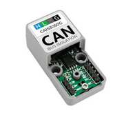
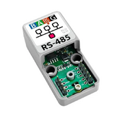
@MrPablo: by the way, unless I misunderstand something, it should be possible to use 2 x CAN OR 1 x CAN + 1 x RS485 OR 2 x RS485 on each ATOM S3 Lite :) .

1711401176555.png + 1711401258284.png


OR
1711401197179.png + 1711401314001.png

OR
1711401176555.png + 1711401314001.png

OR

1711401197179.png + 1711401258284.png


Just some food for though concerning multi-battery communication. But if each JK BMS communicates via BLE/Wire to one of these slaves, then you send everything via CAN/RS485 to the master, then the master talk on the CAN interface to the inverter ...

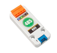
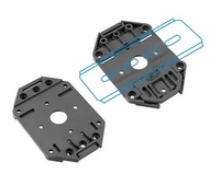
And in my case for DIN Rail Mounting Accesory:
A111 1711401541929.png


Am I missing something ?
 
According to Andy from Off Grid Garage starting balance below 3.43 VDC can result in UNBALANCE, because according to him it's still not steep enough. Are you sure about lowering to 3.43 VDC ?

When I balance a new battery I start at 3.4V to rough out the work. Then in production I use 3.45V with a charging voltage of 55.2V.

To destroy the top balancing, try a value like 3.0V, you will see it is very effective. 🙃, @arzaman
 
When I balance a new battery I start at 3.4V to rough out the work. Then in production I use 3.45V with a charging voltage of 55.2V.

To destroy the top balancing, try a value like 3.0V, you will see it is very effective. 🙃, @arzaman
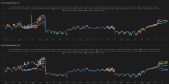
OK something weird is again going on. I didn't implement these measures yet though ...

1711446962833.png

Ignore the left side of the picture around 17h45 ... I tried an OTA update, it got stuck (as usual), then inverter went "full power" (max voltage & current), and both batteries tripped ...

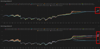
On the right side around 10h45, cell 11 is again behaving very weirdly ... I am not sure what to think ... A miswired balance lead would probably result in a cell going either to the "moon" (OVP) or to the "ground" (UVP). This is not happening ... But as current reduced (when cell 11 turquoise in the plot is "overtaken" by most others). So I'm tending to say it's probably a bad connection / bad cell (ESR is higher, thus current x ESR = voltage is higher during charging at "high" current, but NOT at low current), as @Der_Hannes ands @MrPablo said. The other consequence is of course less energy "reaches" the cell during charging, thus it needs to be "recharged" during the balancing process (which is never taking place fully right now).

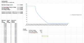
I updated Current Charge Control to 2.00 / 0.40 as below. This seems to make it much more smooth and stable. Thank you for the suggestion ! I think 1.0 was still too much, so I wanted to see how it would go with 0.40. Actually, battery 01 (the one behaving well), liked it quite a bit. Almost until the top of the charge it went full current, maybe only 40-50 A in the last minutes. This is perfect :love:.
1711447184399.png

On the other hand, I cannot say the same for the Charge Voltage Control.
Now I am again having +1A ... -1A in the battery oscillations. This is probably due to the fact that the "Absorbtion Offset V." Parameter gets "dropped" when the "Charging Status" changes from "Bulk" to "Balancing".

As a result it will not balance properly ...

So, on my side at least, I'll try to introduce another parameter "Balancing Offset V." Parameter, probably the same value as "Absorbtion Offset V.", but that I can tune via Home Assistant for now ...

I'll also have a look at the "End of bulk / balancing" conditions as I believe this contributes to the balancing never being done properly.

Besides this I'll make these parameters that can be changed, at least for testing:
float cell_uniformity = 1.0;
float cell_sensitivity = 1.8; // For more aggressive reponse, reduce this number.
float cell_bulk_v = (id(bulk_voltage).state / id(cell_count).state);
float cell_charge_knee_v = 3.400;

Same for these as well
float cv_min = 3.37;
float cv_max = 3.65;


Other issue (or feature ?): using the code here (instead of syssi esphome-jk-bms) my hostname / device name "jk-bms-bat02" is repeated 2 times for all of the sensors.
This is what I have in my Home Assistant Lovelace Dashboard, notice the difference between Battery 01 (syssi code) and Battery 02 (Sleeper 85 code):
YAML:
type: vertical-stack
cards:
  - type: horizontal-stack
    cards:
      - type: history-graph
        entities:
          - entity: sensor.jk_bms_bat01_cell_voltage_1
          - entity: sensor.jk_bms_bat01_cell_voltage_2
          - entity: sensor.jk_bms_bat01_cell_voltage_3
          - entity: sensor.jk_bms_bat01_cell_voltage_4
          - entity: sensor.jk_bms_bat01_cell_voltage_5
          - entity: sensor.jk_bms_bat01_cell_voltage_6
          - entity: sensor.jk_bms_bat01_cell_voltage_7
          - entity: sensor.jk_bms_bat01_cell_voltage_8
          - entity: sensor.jk_bms_bat01_cell_voltage_9
          - entity: sensor.jk_bms_bat01_cell_voltage_10
          - entity: sensor.jk_bms_bat01_cell_voltage_11
          - entity: sensor.jk_bms_bat01_cell_voltage_12
          - entity: sensor.jk_bms_bat01_cell_voltage_13
          - entity: sensor.jk_bms_bat01_cell_voltage_14
          - entity: sensor.jk_bms_bat01_cell_voltage_15
          - entity: sensor.jk_bms_bat01_cell_voltage_16
        title: Cells Voltages Battery 01
        hours_to_show: 24
  - type: horizontal-stack
    cards:
      - type: history-graph
        entities:
          - entity: sensor.jk_bms_bat02_jk_bms_bat02_cell_voltage_01
          - entity: sensor.jk_bms_bat02_jk_bms_bat02_cell_voltage_02
          - entity: sensor.jk_bms_bat02_jk_bms_bat02_cell_voltage_03
          - entity: sensor.jk_bms_bat02_jk_bms_bat02_cell_voltage_04
          - entity: sensor.jk_bms_bat02_jk_bms_bat02_cell_voltage_05
          - entity: sensor.jk_bms_bat02_jk_bms_bat02_cell_voltage_06
          - entity: sensor.jk_bms_bat02_jk_bms_bat02_cell_voltage_07
          - entity: sensor.jk_bms_bat02_jk_bms_bat02_cell_voltage_08
          - entity: sensor.jk_bms_bat02_jk_bms_bat02_cell_voltage_09
          - entity: sensor.jk_bms_bat02_jk_bms_bat02_cell_voltage_10
          - entity: sensor.jk_bms_bat02_jk_bms_bat02_cell_voltage_11
          - entity: sensor.jk_bms_bat02_jk_bms_bat02_cell_voltage_12
          - entity: sensor.jk_bms_bat02_jk_bms_bat02_cell_voltage_13
          - entity: sensor.jk_bms_bat02_jk_bms_bat02_cell_voltage_14
          - entity: sensor.jk_bms_bat02_jk_bms_bat02_cell_voltage_15
          - entity: sensor.jk_bms_bat02_jk_bms_bat02_cell_voltage_16
        title: Cells Voltages Battery 02
        hours_to_show: 24
 
I think it is wise to turn on the 'stop on BMS error' or whatever the setting is called on the Deye inverter. Losing CANbus connection with a resulting full voltage and current charge is a Very Bad Idea.

I'm testing new voltage control logic at the moment, only implemented yesterday however. This may reduce some of the issues you've raised.

As for HA naming, I'm not seeing this on my setup. I wonder if removing the device, then re-adding it would resolve it.

I wonder if we could work together rather than in parallel, because I am not really having fun modifying the code just to have a separate fork to maintain. I'll never understand this about GitHub. Maybe it's just me, but I'd like to have everything merged into the original project (upstream), not having to maintain a fork of my own ...

The naming problem ... Is it maybe due to the old syssi device having the same name ?
I removed it (the old syssi one that I previously disabled) now but the issue persists.

Actually what I said before is not true: on Battery 02 ONLY the cells 01-09 have this "double name" issue.
I wondered why some entities didn't show up in the plot, this is apparently why ...

Working YAML:
YAML:
type: vertical-stack
cards:
  - type: horizontal-stack
    cards:
      - type: history-graph
        entities:
          - entity: sensor.jk_bms_bat01_cell_voltage_1
          - entity: sensor.jk_bms_bat01_cell_voltage_2
          - entity: sensor.jk_bms_bat01_cell_voltage_3
          - entity: sensor.jk_bms_bat01_cell_voltage_4
          - entity: sensor.jk_bms_bat01_cell_voltage_5
          - entity: sensor.jk_bms_bat01_cell_voltage_6
          - entity: sensor.jk_bms_bat01_cell_voltage_7
          - entity: sensor.jk_bms_bat01_cell_voltage_8
          - entity: sensor.jk_bms_bat01_cell_voltage_9
          - entity: sensor.jk_bms_bat01_cell_voltage_10
          - entity: sensor.jk_bms_bat01_cell_voltage_11
          - entity: sensor.jk_bms_bat01_cell_voltage_12
          - entity: sensor.jk_bms_bat01_cell_voltage_13
          - entity: sensor.jk_bms_bat01_cell_voltage_14
          - entity: sensor.jk_bms_bat01_cell_voltage_15
          - entity: sensor.jk_bms_bat01_cell_voltage_16
        title: Cells Voltages Battery 01
        hours_to_show: 24
  - type: horizontal-stack
    cards:
      - type: history-graph
        entities:
          - entity: sensor.jk_bms_bat02_jk_bms_bat02_cell_voltage_01
          - entity: sensor.jk_bms_bat02_jk_bms_bat02_cell_voltage_02
          - entity: sensor.jk_bms_bat02_jk_bms_bat02_cell_voltage_03
          - entity: sensor.jk_bms_bat02_jk_bms_bat02_cell_voltage_04
          - entity: sensor.jk_bms_bat02_jk_bms_bat02_cell_voltage_05
          - entity: sensor.jk_bms_bat02_jk_bms_bat02_cell_voltage_06
          - entity: sensor.jk_bms_bat02_jk_bms_bat02_cell_voltage_07
          - entity: sensor.jk_bms_bat02_jk_bms_bat02_cell_voltage_08
          - entity: sensor.jk_bms_bat02_jk_bms_bat02_cell_voltage_09
          - entity: sensor.jk_bms_bat02_cell_voltage_10
          - entity: sensor.jk_bms_bat02_cell_voltage_11
          - entity: sensor.jk_bms_bat02_cell_voltage_12
          - entity: sensor.jk_bms_bat02_cell_voltage_13
          - entity: sensor.jk_bms_bat02_cell_voltage_14
          - entity: sensor.jk_bms_bat02_cell_voltage_15
          - entity: sensor.jk_bms_bat02_cell_voltage_16
        title: Cells Voltages Battery 02
        hours_to_show: 24

EDIT 1: updated cell voltages plots
1711450232593.png
 
Last edited:
I think it is wise to turn on the 'stop on BMS error' or whatever the setting is called on the Deye inverter. Losing CANbus connection with a resulting full voltage and current charge is a Very Bad Idea.

I'm testing new voltage control logic at the moment, only implemented yesterday however. This may reduce some of the issues you've raised.

As for HA naming, I'm not seeing this on my setup. I wonder if removing the device, then re-adding it would resolve it.
About the "BMS_Err_Stop" setting on the Deye I'd like to have parallel communication working first (maybe implementing it based on @Der_Hannes MQTT code).

I'd like to at least stop the single battery for maintenance / balancing (without allowing discharge, only provide some charging current) without tripping everything.

But based on @Der_Hannes code I'll probably pre-configure everything for 16 batteries, then add some toggle switches to enable each single battery (enable by default all). If enabled, then CCC and CVC will keep that battery into account for min/avg/Nbat*worst_case_parameter/etc. Otherwise not.

I'm tired of this OTA causing disasters since it freezes everything each time :rolleyes: .

EDIT 1: and if Battery doesn't respond, I guess the master should assume a safe voltage (e.g. 53.6 VDC) and limit charge / discharge current to less than half the previous one. Or something like that, I'll see what I come up with.

The main feedback for you devs would be: make ALL parameters editable via Home-Assistant :) .
 
Last edited:
I wonder if we could work together rather than in parallel, because I am not really having fun modifying the code just to have a separate fork to maintain. I'll never understand this about GitHub. Maybe it's just me, but I'd like to have everything merged into the original project (upstream), not having to maintain a fork of my own ...

The main feedback for you devs would be: make ALL parameters editable via Home-Assistant :) .

There's an enhancement issue on the GitHub repository, you're welcome to follow and comment as required.

As for every parameter being exposed, I guess that's personal preference.
For me, the more that is exposed, the more opportunity there is to make mistakes when tweaking things. Many of the parameters are either one time only (on setup) or are somewhat battery chemistry specific.

Re. automatic charge voltage, I would suggest posting on the GitHub issue.
Is that issued based on my comments ? Cannot remember exactly, I modified the spreadsheet quite a bit since ...
 
There's an enhancement issue on the GitHub repository, you're welcome to follow and comment as required.

As for every parameter being exposed, I guess that's personal preference.
For me, the more that is exposed, the more opportunity there is to make mistakes when tweaking things. Many of the parameters are either one time only (on setup) or are somewhat battery chemistry specific.

Re. automatic charge voltage, I would suggest posting on the GitHub issue.
Regarding the parameters etc I can understand your point (as a developer): some users might change without knowing what they are doing.

But especially in cases where it's in production, I cannot reflash, etc, for some quick troubleshooting it can be useful IMHO to give quick feedback.

Otherwise:
  • If BMS_Err_Stop is NOT set, during reflashing Inverter will go full power (max voltage & max current)
  • If BMS_Err_Stop is SET and you reflash "directly", Inverter will trip
  • If BMS_Err_Stop is SET you need to follow a special procedure during reflashing of the ESP32 in order to prevent the previously mentioned issue:
  1. Uncheck BMS_Err_Stop
  2. Change Battery Mode to Voltage. Ensure that Float Voltage, Absorbtion Voltage and Equalization Voltages are "safe"
  3. Flash
  4. Change Battery Mode to Lithium 00
  5. When Inverter shows "Normal", CHECK BMS_Err_Stop as it was previously

EDIT: Updated Formatting
 
Last edited:
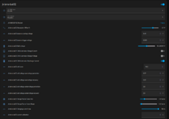
@MrPablo: I turned off Automatic Charge Voltage a while ago since it wouldn't let them charge since voltage was "fixed" in "balancing" charging status.

Now I also turned off Automatic Charge Current, since this also leads to oscillations. Yes, even the 2.0/0.4 coefficient is not smooth enough at that level of voltage ...

Maybe it's a "feature" and not a bug, but maybe automatic Charge Control should only be enabled e.g. above 20% nominal current, not balancing, or at least give it some timer so it doesn't turn into the on-off regulator that we all love :ROFLMAO: . Or some other condition ...

1711457459343.png
 
@silverstone

Excuse me if I ask a question that has already been answered, I'm far from having followed all of your comments.

Concerning your battery #2 have you already carried out a first top balancing and managed to align all your cells at 3.65V with a low charging current?
 
@MrPablo: I turned off Automatic Charge Voltage a while ago since it wouldn't let them charge since voltage was "fixed" in "balancing" charging status.

Now I also turned off Automatic Charge Current, since this also leads to oscillations. Yes, even the 2.0/0.4 coefficient is not smooth enough at that level of voltage ...

Maybe it's a "feature" and not a bug, but maybe automatic Charge Control should only be enabled e.g. above 20% nominal current, not balancing, or at least give it some timer so it doesn't turn into the on-off regulator that we all love :ROFLMAO: . Or some other condition ...

View attachment 204829
I have been unable to replicate your issues.
A zoomed in chart focusing just on the oscillation period would be appreciated.
Please provide requested current & actual current for that same shortened period, as well as the exact settings used for current control, alongside your max charging current, float voltage and OVPR as set in the BMS.
 
@silverstone

Excuse me if I ask a question that has already been answered, I'm far from having followed all of your comments.

Concerning your battery #2 have you already carried out a first top balancing and managed to align all your cells at 3.65V with a low charging current?
It was done 3 weeks ago, but since then it was operating in voltage mode (the Inverter), so only one cell would get above the knee curve of 3.45VDC say. Most were under 3.40VDC. The only option was to set absorbtion and float to 54.4V and 54.3V respectively. Even after top balance, without inverter communication, I cannot set float/absorbtion to 55.2 VDC or 56.0 VDC. It would just cause one cell to shoot up and hit OVP.


Now it's working with your code (well ... until it attempts to top balance at least).

But since then, it got hugely unbalanced again.

I guess this is because it needs to be properly balanced every day, otherwise the unbalance would get worse and worse every day.
 
I have been unable to replicate your issues.
A zoomed in chart focusing just on the oscillation period would be appreciated.
Please provide requested current & actual current for that same shortened period, as well as the exact settings used for current control, alongside your max charging current, float voltage and OVPR as set in the BMS.
Zoom ... Time-wise ? I am not sure how to zoom vertically in these Home Assistant plots at least ...
 
I think it's also time to put an oscilloscope with a HV differential probe on the island grid phases and run some checks.

I installed an EMC filter after the inverter, but my ears keep ringing right now ...

EDIT: Voltage looks clean enough by eye (a bit distorded towards the top, but I still think quite clean compared to e.g. industrial environments). But since it's load dependent, I have no clue what the load at this moment is (no monitoring of inverters / loads yet).
 
Last edited:
Zoom ... Time-wise ? I am not sure how to zoom vertically in these Home Assistant plots at least ...
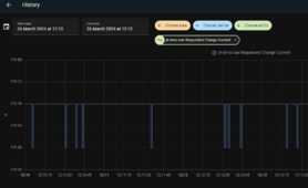
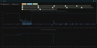
If you go to the history graph for at least one of the entities, you can set a time range like below.
You can add in all the entities that you need to in this pane, then screenshot the whole lot as needed.
1711459137934.png
 
If you go to the history graph for at least one of the entities, you can set a time range like below.
You can add in all the entities that you need to in this pane, then screenshot the whole lot as needed.
View attachment 204833
Thanks.
Here you have them. Is there an option to save those "profiles" of plots somewhere ? It would be easier than having to manually add them one by one each time ...

1711460698721.png
1711460716199.png
1711460743175.png

OVPR is still set at 3.52 VDC
1711460784240.png
 
Back
Top