diy solar

diy solar

JK-BMS-CAN with new Cut-Off Charging Logic (open-source)

Further on in the note it says the higher the current flow you recalibrate at the more accurate it will be.

That also assumes your meters are accurate.
Well it depends if it's an "offset" or "gain" calibration you are after.
Theoretically a calibration for the current would need two points, so you can fit your I = a * x + b current equation of the shunt. Yes, ADCs have offset too ...

If you only calibrate at a single point, I'm not fully sure what is "best".

With a single calibration point:
- If you calibrate at the high end, it will be more accurate at the high end, and less at the low end (more towards "gain" calibration)
- If you calibrate at the low end, it will be more accurate at the low end, and less at the high end (more towards "offset" calibration)
 
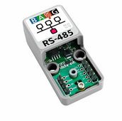
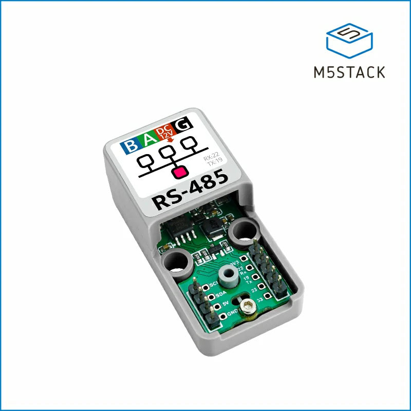
@Der_Hannes: on a separate note (for Inverter Communication via RS485 as well as meters etc), are you are aware of a similar module for RS485 for the Atom S3 Lite ?

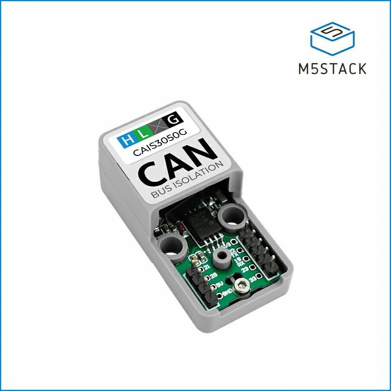
I found this but it doesn't seem to be widely available. It might be even EOL. And it is NOT isolated as far as I can see ...

1711370334376.png


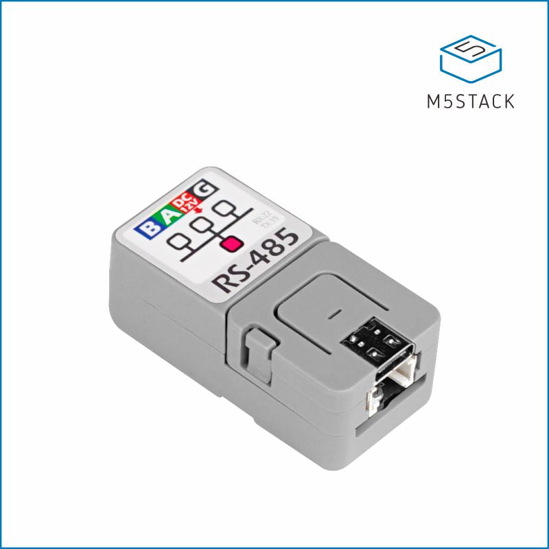
What I bought right now is this one (it IS isolated), but it's true that it's more bulky etc, since it doesn't plug directly into the Atom S3 Lite:
 
@Der_Hannes: on a separate note (for Inverter Communication via RS485 as well as meters etc), are you are aware of a similar module for RS485 for the Atom S3 Lite ?

I found this but it doesn't seem to be widely available. It might be even EOL. And it is NOT isolated as far as I can see ...

View attachment 204561


What I bought right now is this one (it IS isolated), but it's true that it's more bulky etc, since it doesn't plug directly into the Atom S3 Lite:
i dont have any M5stack component yet - ordered on official store but they seem to have trouble providing the correct delivery address...so package was sent back....and now i´m waiting for the second delivery which i have ordered on aliexpress

i recognised the rs485 base and the adapter, but i´m not in need of one. maybe @arzaman can say something about them.

I also recognised, that some kits are EOL - but not the single components.
It would be great if you could help @arzaman. I'd like to start monitoring the Deye Solar production too, not only the Battery control :) .
 
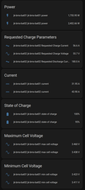
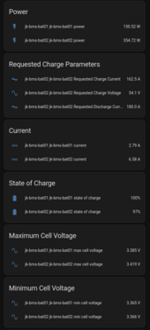
What gives ... Now that I control Battery 02 (worst case), it's Battery 01 that is getting higher now ???

1711371865458.png

This doesn't make any sense.

But it's true that the current is higher than what is used to be in "Voltage Mode" (also the Bulk voltage is higher - 56.4V instead of 55.2V).
 
@Der_Hannes: on a separate note (for Inverter Communication via RS485 as well as meters etc), are you are aware of a similar module for RS485 for the Atom S3 Lite ?

I found this but it doesn't seem to be widely available. It might be even EOL. And it is NOT isolated as far as I can see ...

View attachment 204561


What I bought right now is this one (it IS isolated), but it's true that it's more bulky etc, since it doesn't plug directly into the Atom S3 Lite:
i purchased the CAN bus Isolation from Mstack site - did they run out?
i have 2 of them

let me see if i can dig out the url for you..
 
i purchased the CAN bus Isolation from Mstack site - did they run out?
i have 2 of them

let me see if i can dig out the url for you..

But then taxes on import, high shipping fees, etc
 
@MrPablo: OK, now it's getting weird near the top of the charge.
Charge Current Control seems fine given the voltage (it will drop a lot since I made it very aggressive as soon as the voltage rises).

However requested charge voltage is BELOW float ...
1711373127272.png

1711373161896.png

1711373192583.png

1711373225097.png

EDIT 1: there might NOT be enough solar power available (cloud sky now at ~ 80 W/m2). But still, why is the "reference" (requested) charge voltage getting lowered as a result, while the MAX cell voltage dropped (due to the current decrease) ?

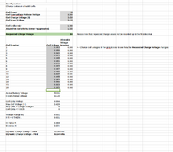
EDIT 2: It's actually consistent with the Spreadsheet ...
1711374026315.png

But in this way it will never be able to balance, wouldn't it ?

EDIT 3: Current Charge control is WAY too aggressive now ... 0 ... +50 A every 5 seconds or so. Then the battery charges/dicharges/charges/discharges etc as a result.

EDIT 4: I think I'll try to edit the YAML file to make those parameters (charge_a_factor_curve_end and charge_a_factor_curve_shape) editable via MQTT / Home Assistant, so I can properly tune it later on. inverter_offset_v should also accept negative values, not only positive ones, IMHO. Why wasn't this done until now ?
 
Last edited:
@silverstone, it's alway possible for you to simply disable the auto voltage control if needed.
The voltage delta you have the moment is quite large considering most cells aren't even near the knee point yet.
You're correct, your battery will not balance with your current settings, especially as I think you set the balance starting voltage to 3.45v.

As an aside, the approach you're taking to prevent a cell from exceeding 3.45v is likely to make it harder to reach that balance starting voltage, surely?

I do wonder if you'd have more success using the default charge current control settings, plus setting the balance starting voltage to 3.43v or so.
That way you'll have more current going in, the max cell would likely reach the balance starting point and so on.

I'll be honest, the tone of some of your queries comes across as somewhat combative. Inverter_offset_v accepting negative values never came up in original testing, etc, so wasn't considered. Documentation might not contain GPIO assignments for hardware not explicitly mentioned.
It's user experience like this that will reveal changes. As they come up, code is enhanced, settings tweaked and contributions expected on GitHub.
This is a hobbyist project after all, with people contributing in their spare time.

Definitively it's true that it's 100% preventing ANY cell from reaching 3.45 V. As soon as one exceeds it, current is reduced to zero (negative actually). The Overaggressive Charge Current Control doesn't really help I guess ...

Not really combative, I was merely asking if those features could be included :) .

Because well, I can always do it from my heavily modified configuration file (which has a different file name etc) and open a pull request on github, same for the documentation enhancement, but is that really the most efficient approach :rolleyes: ?

You'd have to reverse engineer my entire file for a handful of modifications ...

EDIT 1: If I disable the Charge Current Control altogether one cell will reach OVP ... Turned CCC ON again before it did that.

EDIT 2: I'll try to do these modifications on my end, then I'll do a PR ...
 
Last edited:
Because well, I can always do it from my heavily modified configuration file (which has a different file name etc) and open a pull request on github, same for the documentation enhancement, but is that really the most efficient approach :rolleyes: ?

You'd have to reverse engineer my entire file for a handful of modifications ...
Yes, it is the most efficient approach for us - cause we are currently working on the new release as you might noticed.

But it will only be efficent if contributions are made on the currently available version on Github - we don´t have the time to cherrypick relevant things of your modified code.

I just have the feelings, we cannot support yet any setups with more than one battery - there are too much variables to consider cause every setup is different. We are not at that point yet and having an uncontrolled battery connected makes things alot harder for everyone.
Yeah, I'm also not sure what to do about multi battery.

Lazy man approach would tell me either your mqtt solution or just combine several slaves in nodered (once I get that up & running) and "drive" a master ...
 
I'll see what i can do. I'll do a fork. Do you want me to update EVERY YAML file also Li-Ion ? Or just one to test the principle ?
 
I managed to balance battery 01.

Charge current control MUST be disabled... It makes my system unstae, even with the default curve settings.

For battery 02 still a while to go.

But... Bug or feature? If BMS charge switch is turned off, then discharge current is sent as 0 to inverter which trips is PV power is not sufficient.

I just tripped my off grid system because I didn't want battery 02 to discharge so I could rebalance it....
When you have time, please could you share a graph showing max cell voltage, requested charge current and actual current, covering the period where you had default curve settings?
What exactly do you mean by unstable?

Regarding 'If BMS charge switch is turned off, then discharge current is sent as 0 to inverter', I assume you mean BMS discharge switch?
If so, then yes, the code will set discharge amps to 0.

Code:
// Stop Discharging if BMS or ESP32 switch is OFF
if ((!id(bms_switch_discharging).state) | (!id(can_switch_discharging).state)) discharging_a = 0;
Yes, I meant discharge, sorry. My hands were freezing in the garage and I almost couldn't move my fingers. Need to get used to have inverter communication :ROFLMAO: . Before it was like ... "I don't want this battery to get discharged, just turn off the BMS switch". Not so anymore. I guess I'll need to do something like @Der_Hannes did using MQTT for multi battery communication. It's starting to get critical.

Unstable I mean that when the charge current control is enabled, the ESP32 would do like ... 0A ...50A ... 0A ... 50A. Then the voltage start swinging up and down, also affecting the charge VOLTAGE control. And, I believe due to inverter measurement tolerances, the ACTUAL current becomes negative (i.e. the batteries get DISCHARGED).

So I had to disable Current Charge Control in order to slowly (manually sigh :rolleyes: ... the ESP32 entered "float" state, thus Voltage Charge Control is DISABLED - Again ... Bug or Feature ?, so I slowly ramped up float voltage up to 56.4 V in order to force a top balance), otherwise it would basically charge - discharge - charge - discharge.

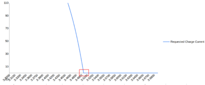
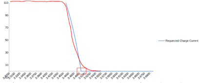
My mathematical feeling is that the first derivative of the Charge Current Control Reference is discontinuos, i.e. the transition point around 0 is NOT "smooth" (curved). It's too "pointy".
1711389105686.png

In order to be much more smooth it should be more of a kind of (in red)
1711389271136.png

But maybe it's also mostly measurement tolerances related.

EDIT: I'll give you the graphs after dinner. Home Assistant is SO SLOW to add these items in history graph. The individual cells voltages basically make Home Assistant so unresponsive in unusable.
 
@MrPablo Here are the courbes. Note that I tried to tune it down to 1.5 instead of 2.0 after a while ...
1711390531587.png
1711390547883.png
1711390564638.png
1711390581811.png
1711390596239.png


Note that in order to give sligthly more headroom for the balancer to work, I raised OVP to 3.57 V (instead of 3.55 V) and OVPR to 3.52V (instead of 3.50V).

Note how "full" (lots of ups and dows) the requested charge current is jumping around 14h45 and 17h00 in particular. And note how the actual current oscillates around 0 at those times.
 
Several thoughts for you:
  • Try increasing OVPR to 3.55v - that'll reduce the steepness of the current reduction as you increase the voltage range over which current is reduced.
  • Don't increase the float voltage as that increases the steepness. Current tapering starts from float voltage.
  • Set the maximum charge current to a lower value, perhaps 100A at most. For example if max is normally 180A, the steepness will increase.
    • This is something that can be changed. My personal code several months ago had a fixed starting current at the knee point.
  • Reducing the curve shape factor could be an option, you could go for something like 1 as it starts to become more linear at that point.
Dynamic CVL is only applied during the bulk, balance and absorption phases, float will always be at the configured voltage.
If your battery is going into float stage, then a cell must be higher than the cutoff voltage, current below the cutoff.
I would suggest lowering your balance start voltage to 3.43v. If your cells are balancing then the current status will not go into float.

That current oscillation is very extreme considering the max cell voltage range. I'm a believer in setting OVP and OVPR to values that protect the battery, but don't reduce the window in which the cells can operate.
After all, this dynamic CCL is designed to prevent OVP, not necessarily maintain a set cell voltage.
 
Last edited:
Several thoughts for you:
  • Try increasing OVPR to 3.55v - that'll reduce the steepness of the current reduction as you increase the voltage range over which current is reduced.
  • Don't increase the float voltage as that increases the steepness. Current tapering starts from float voltage.
  • Set the maximum charge current to a lower value, perhaps 100A at most. If max is normally 180A, the steepness will increase.
    • This is something that can be changed. My personal code several months ago had a fixed starting current at the knee point.
  • Reducing the curve shape factor could be an option, you could go for something like 1 as it starts to become more linear at that point.
Dynamic CVL is only applied during the bulk, balance and absorption phases, float will always be at the configured voltage.
If your battery is going into float stage, then a cell must be higher than the cutoff voltage, current below the cutoff.
I would suggest lowering your balance start voltage to 3.43v. If your cells are balancing then the current status will not go into float.

That current oscillation is very extreme considering the max cell voltage range. I'm a believer in setting OVP and OVPR to values that protect the battery, but don't reduce the window in which the cells can operate.

Thank you for your reply.

1. So setting OVP = 3.60 VDC and OVPR = 3.55 VDC ?

2. The reason I was "playing" with float is that I need to force a top balance. And the "CAN force bulk (top balance)" did not do anything when I tried it. It actually LOWERED the charge voltage to 52.8 V (which is the rebulk voltage).

3. Indeed if I lower the Maximum Charge Current, then it doesn't swing to those extremes. Going from 180A to 50A or 40A made it much more stable. But it's something that needs to be done manually :( .

4. Uhm ... OK. I can try that, I can change it in real time now :ROFLMAO:

According to Andy from Off Grid Garage starting balance below 3.43 VDC can result in UNBALANCE, because according to him it's still not steep enough. Are you sure about lowering to 3.43 VDC ?

So what is controlling the float transition exactly ? Sounds the same as Victron Smartshunt does (Pack Voltage > threshold, Tail current < 0.5% or so, time > 10 min or so). Is it only if ONE cell goes above the threshold ? I would have guessed that ALL cells need to be higher. Otherwise it will not work in my case ...
If you're fighting imbalance now, starting at 3.43v to get it under control then increasing to 3.45v later on makes sense to me.
3.45v is fine if you're regularly going to take cells above that, but if the target is 3.45v then the balance time is much shorter.

The float transition is controlled by three factors, all of which need to be met for charge to terminate and float started.
- BMS balancer is not active, so either cell delta is below the threshold or cell voltage is below trigger voltage.
- Max cell voltage is above the cutoff voltage.
- BMS current is below the cutoff current.
As long as your cells are balancing, charge would continue even at very low current.

These cutoff values are dynamically calculated, but the logic is here.
Right now, some of the development team are testing out a time threshold, so the above conditions would need to be met for 60s (for example) in order to terminate charge. In v1.17.4, charge is terminated as soon as the conditions are met.
 
Back
Top