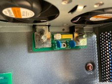
did the precharge let a bulb with auto volatage connected for over a minute then after try connecting negative got sort circuit as before .got a friend to bring me an inverter to see if it is inverter or battery apparently it work with his inverter ,do you think the problem is in pic attach .


You are using an out of date browser. It may not display this or other websites correctly.
You should upgrade or use an alternative browser.
You should upgrade or use an alternative browser.
Overkill BMS connecting Inverter = short circuit! Help!!
- Thread starter SolarHawaii
- Start date
Hedges
I See Electromagnetic Fields!
- Joined
- Mar 28, 2020
- Messages
- 21,833
If bulb remained lit for a minute, then it seems like inverter is shorted.
"Auto voltage" meaning 12V? OK to test for shorts, not sufficient to precharge for 48V battery.
A 120V bulb (or four 12V bulbs in series) would work for 48V.
Friend's inverter works? Or at least precharges until light goes out? But yours does not?
Sounds like your inverter is dead. Did it ever work? Might it have ever been connected backwards?
i am thinking iverter i sshortedIf bulb remained lit for a minute, then it seems like inverter is shorted.
"Auto voltage" meaning 12V? OK to test for shorts, not sufficient to precharge for 48V battery.
A 120V bulb (or four 12V bulbs in series) would work for 48V.
Friend's inverter works? Or at least precharges until light goes out? But yours does not?
Sounds like your inverter is dead. Did it ever work? Might it have ever been connected backwards?
Hedges
I See Electromagnetic Fields!
- Joined
- Mar 28, 2020
- Messages
- 21,833
I'm not sure of the internal architecture. It appears the battery input is shorted (if light bulb for precharge remains on indefinitely, and battery reports short circuit), but PV to AC path works.
If battery input terminals are different impedance from another identical working unit, that suggests something is wrong. Compare apples to apples, each inverter identically connected (or not) to PV and loads.
If battery input terminals are different impedance from another identical working unit, that suggests something is wrong. Compare apples to apples, each inverter identically connected (or not) to PV and loads.
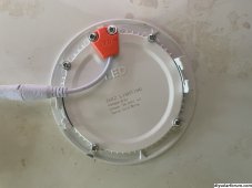
here is what i use to precharge check pics out, who that have been sufficientI'm not sure of the internal architecture. It appears the battery input is shorted (if light bulb for precharge remains on indefinitely, and battery reports short circuit), but PV to AC path works.
If battery input terminals are different impedance from another identical working unit, that suggests something is wrong. Compare apples to apples, each inverter identically connected (or not) to PV and loads.
Attachments
Hedges
I See Electromagnetic Fields!
- Joined
- Mar 28, 2020
- Messages
- 21,833
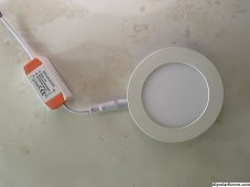
here is what i use to precharge check pics out, who that have been sufficient
Connect a resistor in series (or an incandescent light bulb.

Incandescent light bulb - Wikipedia
think i will get 4 12v automobile bulbs in series easier for meIncandescent light bulb - Wikipedia
en.wikipedia.org
yes have a meter will checkHave a DMM or volt meter?
Useful to monitor and diagnose.
Quattrohead
Solar Wizard
Incandescent bulb is the most simple and clever tool in an electrician's tool box.
do i just need one incadescent bulb ?Incandescent bulb is the most simple and clever tool in an electrician's tool box.
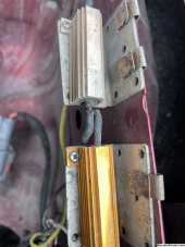
Can use one of those resistors please thank you.Can anyone give me the step by step method please of the precharging thank you.
Attachments
Hedges
I See Electromagnetic Fields!
- Joined
- Mar 28, 2020
- Messages
- 21,833
Here's how to build it into a switch:

 diysolarforum.com
All you do with the light bulb is use it to complete circuit between cable terminal and stud. If light glows then slowly goes dim and goes out, time to put terminal on stud.
Sure, those resistors should work. What resistance values?
Inverter Disconnect Switch with Precharge
To get the paper, click on the orange button at the top of this page. This circuit is designed as a disconnect switch that allows the user to pre-charge the inverter capacitors before turning the switch completely on. 26 June 2020 update: At...
diysolarforum.com
All you do with the light bulb is use it to complete circuit between cable terminal and stud. If light glows then slowly goes dim and goes out, time to put terminal on stud.
Sure, those resistors should work. What resistance values?
ok it 40 ohms and should i have the inverter in a off position please thanks.Here's how to build it into a switch:
Inverter Disconnect Switch with Precharge
To get the paper, click on the orange button at the top of this page. This circuit is designed as a disconnect switch that allows the user to pre-charge the inverter capacitors before turning the switch completely on. 26 June 2020 update: At...
All you do with the light bulb is use it to complete circuit between cable terminal and stud. If light glows then slowly goes dim and goes out, time to put terminal on stud.
Sure, those resistors should work. What resistance values?
Hedges
I See Electromagnetic Fields!
- Joined
- Mar 28, 2020
- Messages
- 21,833
Does the inverter have a circuit breaker to turn it off? Or a low power switch.
(My Sunny Island has a circuit breaker which isolates its capacitor bank from input, so I would have to turn that breaker on before precharge.)
Ideally you precharge the capacitor before inverter starts operating. Because it might consume 25 to 50W no-load, which is 0.5A to 1.0A, would prevent complete precharge.
Try with the inverter off. Precharge, observe voltage riding with a meter (may be quick.) Then connect cable if voltage came up. Then turn on inverter.
50V / 40 ohms = 1.25A
1.25A x 50V = 60W
That is OK. If it gets too hot to touch during precharge, there is a short and you need to stop before overheating the resistor. (It is probably rated for 50W or 100W, but needs a heatsink to handle that continuously.)
A 120V 100W lightbulb has its advantages.
ok do i have to keep battery breaker and bms off also ?Here's how to build it into a switch:
Inverter Disconnect Switch with Precharge
To get the paper, click on the orange button at the top of this page. This circuit is designed as a disconnect switch that allows the user to pre-charge the inverter capacitors before turning the switch completely on. 26 June 2020 update: At...
All you do with the light bulb is use it to complete circuit between cable terminal and stud. If light glows then slowly goes dim and goes out, time to put terminal on stud.
Sure, those resistors should work. What resistance values?
Hedges
I See Electromagnetic Fields!
- Joined
- Mar 28, 2020
- Messages
- 21,833
You would turn battery & BMS on. So it supplies power through the resistor to precharge power.
It helps if you understand where current is flowing, and what components do.
I'm just winging it, don't even have a schematic of your circuit.
diysolarforum.com
It helps if you understand where current is flowing, and what components do.
I'm just winging it, don't even have a schematic of your circuit.
Why is solar so damn difficult?
I've found the lutron casetta stuff to be very reliable.(although not looking forward to the day I need to replace the batteries in all the remotes) Oh yeah. Battery replacement lol. But that's every 10 years though -so they say. I'm in the same boat. I've got a bunch of Bluetooth temperature...
diysolarforum.com
Levo
Alberta Glamper
This thread title seemed to fit, so hopefully a good place to start.
Just reinstalled my 280Ah LiFePO4 battery after winter storage, reading very close to 13v no load. Everything was still how I left it in October, SCC, B to B charger and 1600w LF inverter all connected to buss bars only. I tried to switch on the battery via overkill bluetooth, but no go. Just a red "short circuit" message. I tried a few times.
Decided to remove inverter connection from the buss bars; sure enough the battery powered up, house lights came on as did the SCC screen. At first my meter across the 12v +/- inverter connections showed "continuity". Then intermittently it went to reading "open circuit" and short again minutes later.


Now the inverter is on the bench and across the terminals it still reads open. I can't find anything loose to wiggle and bring back the short. This inverter has not skipped a beat since installation 2 years ago, and has seen no excessive loads or physical trauma.
What should the ohm meter read across the low voltage side? Would really appreciate a path forward if anyone has ideas. Thanks.
Just reinstalled my 280Ah LiFePO4 battery after winter storage, reading very close to 13v no load. Everything was still how I left it in October, SCC, B to B charger and 1600w LF inverter all connected to buss bars only. I tried to switch on the battery via overkill bluetooth, but no go. Just a red "short circuit" message. I tried a few times.
Decided to remove inverter connection from the buss bars; sure enough the battery powered up, house lights came on as did the SCC screen. At first my meter across the 12v +/- inverter connections showed "continuity". Then intermittently it went to reading "open circuit" and short again minutes later.
Now the inverter is on the bench and across the terminals it still reads open. I can't find anything loose to wiggle and bring back the short. This inverter has not skipped a beat since installation 2 years ago, and has seen no excessive loads or physical trauma.
What should the ohm meter read across the low voltage side? Would really appreciate a path forward if anyone has ideas. Thanks.
ScrotpusGobbleBottom
Corn Pop was a bad dude.
I thought precharge was only to protect the battery/BMS from overcurrent tripping?That is needed for many lithium battery & inverter circuits.
Hedges
I See Electromagnetic Fields!
- Joined
- Mar 28, 2020
- Messages
- 21,833
Protects from overcurrent tripping, or blowing fuse or welding contacts or damaging capacitors.
Lots of things can get damaged by multi-thousand amps spikes.
Soft-start circuits are designed into many products, but few have the massive surge of these lithium batteries.
Lots of things can get damaged by multi-thousand amps spikes.
Soft-start circuits are designed into many products, but few have the massive surge of these lithium batteries.
Hedges
I See Electromagnetic Fields!
- Joined
- Mar 28, 2020
- Messages
- 21,833
What should the ohm meter read across the low voltage side? Would really appreciate a path forward if anyone has ideas. Thanks.
Try giving battery a recharge (With suitable CV/CC supply.)
Levo
Alberta Glamper
I don't have a CV/CC supply, just an old school charger for FLA. The battery is receiving solar charge from the SCC as we speak, so I should be able to see if bringing up the voltage helps. Thanks for the suggestion.Try giving battery a recharge (With suitable CV/CC supply.)
Also, just connected the inverter to a FLA deep cycle battery (showing 12.5v unloaded) and I have 115v at the output side. What the hell?
Similar threads
- Replies
- 9
- Views
- 529
- Replies
- 0
- Views
- 264
- Replies
- 13
- Views
- 981