That line filter most likely cleans up differential mode RFI followed by ferrite to choke common mode.I found a link and I noticed the guy put the LC filter before the toroids (he ie using type 31 and type 43). I wonder if that matters.
You are using an out of date browser. It may not display this or other websites correctly.
You should upgrade or use an alternative browser.
You should upgrade or use an alternative browser.
RFI issue
- Thread starter Cagire
- Start date
wpns
Solar Joules are catch and release
And of course, if you have RSD make sure you don't block the enable frequency, though I think that's in the 150KHz range...
My RFI issues came from the SCC and a Mix31 on each wire dropped from S9 to barely perceptible. The higher the frequency, the worse it was from me. Someone mentioned cheap getting rid of cheap inverters and chargers but my Victron 250/100 is much worse than a BougeRV 60a SCC, virtually silent with no filtering.
Additionally, paralleling the Mix31 cores physically from each wire together, further reduced it.
Additionally, paralleling the Mix31 cores physically from each wire together, further reduced it.
wpns
Solar Joules are catch and release
Ah, now that I think about it, the MPPT is going to be differential mode, so common mode chokes aren’t going to help a lot.Additionally, paralleling the Mix31 cores physically from each wire together, further reduced it.
Hedges
I See Electromagnetic Fields!
- Joined
- Mar 28, 2020
- Messages
- 21,483
Here is the new way:
View attachment 208374
Note that I removed the ground from the inverter because I needed to bond the neutral to the ground anyway in offgrid mode, which I do with a relay) :
Filter at ground
View attachment 208376
Separate choke around ground, and isolating inverter chassis, don't feel right from an EMI point of view (and isolating from safety point of view.)
L/N/G all through a choke seeks to keep sum of those currents equal to zero.
Inverter may have LC filters in power line, with noise injected into chassis. I think that should have hard connection back to earth, so nothing is driven common-mode relative to earth. (going through same choke as L & N should be good.)
Common-mode chokes are what is typically added as band-aid for EMI. LC filters could help, more difficult to size properly and install, of course.
Hedges
I See Electromagnetic Fields!
- Joined
- Mar 28, 2020
- Messages
- 21,483
I hadn't thought of MOV to protect cap. Cap for AC line ought to withstand kV transients typically seen on lines.
LC filter as you describe matches what I was thinking of.
For PV, some inverters spec max capacitance to ground for panels because they do a leakage check and superimpose AC. I think the leakage check is brief grounding of PV- and of PV+, so capacitance would be a momentary current flow. The inverters I have, looks to me like feeding 208V of 3-phase drives 60 Hz 60Vrms common mode, 240V single phase drives 120V, 120/240V split-phase doesn't drive AC.
The square wave you mention, is that MPPT or is it due to non-isolated from AC?
RSD keep-alive or communications would be differential mode current. If using external keep-alive transmitter, just put these filter components between that transmitter and the inverter. If internal, don't want to kill the signal with capacitance between the two lines. What bandwidth? filter could have band pass, in this case "band not stop" since it is a shunt.
You may be able to put capacitance from a single wire PV- to ground but not PV+ to ground, so keep-alive isn't absorbed. Of course, that asymmetry would convert common-mode noise to differential. Basic problem is passing desired signal and blocking the rest. Chokes before and after the shunt capacitance, band pass filter to jumper around it?
Ah, now that I think about it, the MPPT is going to be differential mode, so common mode chokes aren’t going to help a lot.
Just a bulk capacitor which passes (shunts or shorts) MPPT frequency ought to work. Needs to not affect keep-alive frequency. An inductor in series with cap could tune to be high frequency for that. Does low impedance to 15kHz MPPT, high impedance to 150kHz keep-alive sound right? one decade, about 20 dB. Not huge, but something.
I'm a bit lost to be honest, I'm not so advanced in electronics sadly ...
If I recap, you suggest twisting N + L + G and wind them in the same toroid on AC-output, right ? Same for DC-panels-input or not ?
No I don't, I have a little oscilloscope though, if it can be any usefull.
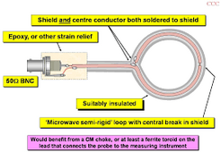
Do you mean something like this ?

I could build one I guess.
If I recap, you suggest twisting N + L + G and wind them in the same toroid on AC-output, right ? Same for DC-panels-input or not ?
I don't think you know which wires are the radiator.
Have a sniffer probe or clamp current probe good for the frequency of interest? Check for common-mode and differential mode on each cable/wire.
No I don't, I have a little oscilloscope though, if it can be any usefull.
Do you mean something like this ?

I could build one I guess.
Non-isolated from AC. Low frequency 50Hz commutating half-bridge of DC-AC inverter stage connects N wire to positive internal HVDC rail and on alternate half cycle to negative rail. When it connects positive to neutral it causes PV- to become negatively biased in relation to ground by HVDC voltage typically -450V.The square wave you mention, is that MPPT or is it due to non-isolated from AC?
Hedges
I See Electromagnetic Fields!
- Joined
- Mar 28, 2020
- Messages
- 21,483
I'm a bit lost to be honest, I'm not so advanced in electronics sadly ...
If I recap, you suggest twisting N + L + G and wind them in the same toroid on AC-output, right ? Same for DC-panels-input or not ?
No I don't, I have a little oscilloscope though, if it can be any usefull.
Do you mean something like this ?
View attachment 208684
I could build one I guess.
Something like that. Maybe that shielded coax is better by rejecting voltage coupling.
I've tried a simple loop of wire, later bought a couple near-field HP probes. But I got better results using a pre-amp as well. Voltage sensitivity of some oscilloscopes is only about 1mV. The conducted EMI on AC limit per FCC is about 1mV.
If your scope has FFT, that can pick up tones well below the noise floor, extending dynamic range.
(surprising, but it works. It can see signals 1/10th of one ADC LSB.)
Just a loop of wire held in parallel with each suspect cable or wire should pick up inductively coupled current. That way you could figure out which cable is the radiator - AC, PV, battery, communications.
Or feed into your receiver, which has no trouble seeing the even smaller signal at a distance.
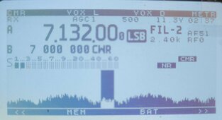
With a loop on a BNC on the receiver, I'm not able to pick up any signal from the cables right now. I think the suppression is quite efficient, to be honest. From the very short tests performed on the radio and my normal antenna, I would say 80% of RFI has been suppressed compared to before the work.
Nevertheless, I'm picking up a strong signal when sniffing on the top and bottom of the inverter itself, very wide peaks every 20 kHz, with smaller ones in between.

Nevertheless, I'm picking up a strong signal when sniffing on the top and bottom of the inverter itself, very wide peaks every 20 kHz, with smaller ones in between.

You may be picking up magnetic fields from currents inside the inverter or inverter enclosure is radiating. There is another way to test common mode current radiating over wires connected to inverter. Take clamp on ferrite core or split core and clamp it on a pair of wires, for example AC out and feed one turn of your BNC loop through that ferrite core also. This will form a transformer with AC wires as primary and BNC loop as secondary. Common mode current will get coupled into BNC loop and will be received by your radio. Simply placing BNC loop next to wire to be tested provided too little coupling to be sensitive.
Hedges
I See Electromagnetic Fields!
- Joined
- Mar 28, 2020
- Messages
- 21,483
How big are slots in the enclosure? Including distance between screw, unless there is gasketing.
Shielding ("Faraday Cage") only works far-field. If there is a magnetic component inside, it will reach right through the sheet metal and induce current in another wire, so that sniffing is not conclusive.
(Antron typed faster than me.)
Shielding ("Faraday Cage") only works far-field. If there is a magnetic component inside, it will reach right through the sheet metal and induce current in another wire, so that sniffing is not conclusive.
(Antron typed faster than me.)
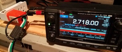
Here is my 705 picking up S9+20 RFI from my Victron inverter with one loop of wire through clamp on core on AC wires. Clamping on additional choke on that AC wire produced 2 dB reduction of receiver signal. This method is very sensitive. Also it has to be battery powered receiver isolated from mains power as to not create interfering path for RFI. This RFI is undetectable on my backyard dipole with constant S8 RFI on 80m band from neighbors.


Hedges
I See Electromagnetic Fields!
- Joined
- Mar 28, 2020
- Messages
- 21,483
A whole 2 dB!
If you make multiple turns through that additional choke, does it attenuate much more?
Where I did this successfully, problem had been improperly grounded RJ45 emitting and coupling to power line.
I did 3 turns through a ferrite with shielded patch cord, then put into shielded female/female bulkhead RJ-45 connector, and grounded that connector. This let us pass FCC testing at EMI lab. 3 turn choke by itself hadn't, and grounded bulkhead connector hadn't, or so I'm told.
For this power cord mitigation, it could mean grounding the ground wire after the additional choke. And attaching sniffer pick-up after the ground.
Yes it does. 3 turns will create 13 dB attenuation on 3.8 Mhz.f you make multiple turns through that additional choke, does it attenuate much more?
There is no ground, that green wire is floating. Solar panels, MPPT, battery, inverter and load (midea air con I am running on inverter at the moment) are all floating disconnected from earth ground. RFI common mode current is created by long ac power cord antenna effect. With this configuration Victron low frequency inverter (Phoenix 800VA) is undetectable under suburban RFI environment. Their Smart Solar MPPT on other hand is a broadband spike generator on HF mostly on 40m band.For this power cord mitigation, it could mean grounding the ground wire after the additional choke. And attaching sniffer pick-up after the ground.
Last edited:
Out of curiosity I calculated common mode current flowing over that AC power cord assuming perfect 1 to 1 transformer coupling. So the reading on the radio is S9+20 = 53 dBm = 0.000000005 watts. Converting to volts at 50 ohms = 0.5 mV / 50 ohm = 0.01 mA or 10 micro amps. To get exact common mode current I would have to measure coupling loss of that split core transformer at frequency of interest. That result would only measure current in receiver bandwidth of around 3 kHz. Total common mode current will have to be measured with broadband RF detector of 0.1 - 30 Mhz BW. But this method using HF receiver is good enough for testing attenuation effect of ferrite chokes.
Last edited:
Hedges
I See Electromagnetic Fields!
- Joined
- Mar 28, 2020
- Messages
- 21,483
No ground, so whatever EMI filter Midea has, it's shunt caps don't have anything to dump current into.
Come to think of it, that's the case with a 3 prong to 2 prong adapter when no grounded screw is available, or GFCI outlet on 2-wire circuit. Like all the PCs in my "new" house.
0.5 mV? I think that's just under 1 mV FCC limit. For conducted EMI frequencies up to 30 MHz.
What frequency do you see?
Higher frequencies would be radiated EMI limit, V/m at some distance.
Nothing grounded is an interesting case, no leverage to drive currents in a wire (e.g. short whip antenna for low frequencies). Higher frequencies, various ways to make standing waves.
This was at 2718 kHz where RFI was strongest. Everywhere else its much less. PV wire is ~100 feet and AC power cord out of inverter is 50ft both ran in same direction separated by 10 feet, creating sort of J-pole antenna on the ground effect.
Last edited:
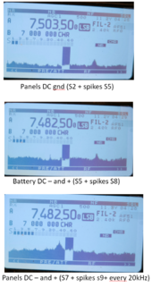
Looks like your PV wire may still be the source of your remaining RFI. This could be due to PV- wire hard switching -450V at 50Hz in relation to ground with lots of ringing as well. That creates strong RFI due to dV/dt and halfbridge IGBT ringing. So we have to figure out how to filter that without excessive capacitive loading on those IGBTs.
This was at 2718 kHz where RFI was strongest.
I was wondering how you picked that frequency.
wpns
Solar Joules are catch and release
I didn't think he _picked_ that frequency, I read it that he _measured_ that frequencyI was wondering how you picked that frequency.
Similar threads
- Replies
- 76
- Views
- 4K


