ABarbarian
New Member
- Joined
- Mar 13, 2022
- Messages
- 48
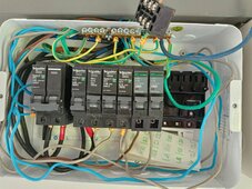
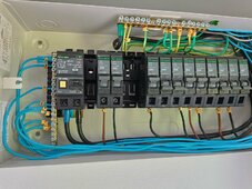
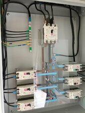
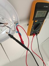
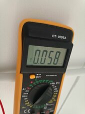
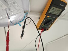
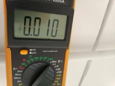
See pics, yes when glowing there is 0.09 Amps passing throughI'd still like you to run the N in series with your multimeter and see what you get.


See pics, yes when glowing there is 0.09 Amps passing throughI'd still like you to run the N in series with your multimeter and see what you get.
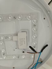
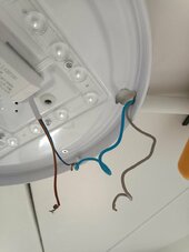
Attached are pictures of the LED and some wiring.Your inverter is putting out some HF noise and the capacitance of the cable is enough to supply power to the LED
That must me erroneous reading. 230V * .09A = 20.7 Watts.See pics, yes when glowing there is 0.09 Amps passing through
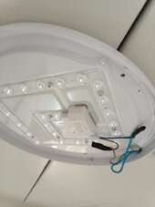
Only L and N wires, which makes me think it can't be current passing to Ground?Could you open up your LED light and show what it looks like and show the circuit board it uses? Does it have L, N, and Ground wires or just L and N wires? Edit: I now see images you posted at the same time I wrote this.
What kind of light switch do you have? Is it purely mechanical or electronic?

See pics, yes when glowing there is 0.09 Amps passing through


Just a quick reply: 115 V is Neutral to Ground, but no ground wire is coming into the lamp, roof is cement and conduit plastic so I am confident there is no grounding of the lamp, and current passing across N-G's 115V is not applicable to the glow.We know you've got 115 volts on the neutral
So you do have a 2-terminal device? Either your switch isn't isolating enough (try detaching the wires from your switch, cleaning the insulation and ends, and separating them by a few inches, to have a really open circuit), or there's something to the RFI scenario.Just a quick reply: 115 V is Neutral to Ground, but no ground wire is coming into the lamp, roof is cement and conduit plastic so I am confident there is no grounding of the lamp, and current passing across N-G's 115V is not applicable to the glow.
No glow when the circuit is on direct grid supply makes me feel the switch is probably not leaking current through line, and there is no ground, so it feels like there is no traditional circuit here causing Amp flow.
I like efficientPV's theory that the "inverter is putting out some HF noise and the capacitance of the cable", although my understanding of this is near nothing.
I think the attached pictures fix my measuring technique.To get accurate measurements of less than 1 amp (mA range) one needs to use a DVM and run the circuit through it in series
Switch is a simple mechanical switchSo you do have a 2-terminal device? Either your switch isn't isolating enough (try detaching the wires from your switch, cleaning the insulation and ends, and separating them by a few inches, to have a really open circuit), or there's something to the RFI scenario.
I was using an incorrect multimeter in my first set of readings, I think I fixed that. The probes were connected to try and read what Amps were passing through, I just made a post about the results.Looking at pictures of the lamp, why are the probes connected? Current is thru the clamp. Connect brown and blue together and also connected to one leg of power. That would determine if there is leakage to concrete.
Reversing brown and blue would also be an interesting test for leakage.
I am not sure it is relevant, because the glow persists when inverter is set on bypass mode and there is no voltage difference between N-G, I believe in that situation the inverter is not doing much, it is passing through the grids power (however my issue suggests the inverter or inverter cabling is doing "something" because the glow disappears when powered directly from grid).This requires only one polarity of 170 V power supply, so it’s cheaper, but means that output “neutral” is actually at 170 V with respect to ground for part of each cycle of the output.
It is also possible to create AC at the battery voltage, using only a single polarity of supply, using either a single primary winding and a 4-transistor H-bridge (the 2nd design above), or a center-tapped transformer and 2 transistors. Then the voltage is stepped up to line voltage by the transformer. Since the transformer secondary is isolated, it can be connected with the neutral output grounded. But transformers cost money and also add extra weight.
And that’s probably why you measure voltage on neutral on your inverter: It is probably using an H-bridge type design at line voltage, without a step-up transformer."
Any relevance to our situation?
I am not sure it is relevant, because the glow persists when inverter is set on bypass mode and there is no voltage difference between N-G, I believe in that situation the inverter is not doing much, it is passing through the grids power (however my issue suggests the inverter or inverter cabling is doing "something" because the glow disappears when powered directly from grid).