diy solar

diy solar

Inverter PV Size?

Yes. I was about to post a message regarding this.

(There's plenty of confusion on this in otherwise pretty reputable blog posts. That's why I think this is tickling the math dragon a bit. But you have no choice if you are backfeeding into an existing subpanel. For instance I backfeed my solar into a subpanel that is fed with 100A from my main)
If my AHJ had accepted my DIY grid tied permit application two years ago I would've been living in this world, my house is a big string of 3 subpanels all fed by a single case molded circuit breaker disconnect, sort of like OP's situation.
 
I thought you could leave a 100A (or 200A, whatever is appropriate for the wiring) subpanel breaker on the Addition panel, and rely on the fact that there is only a 65A solar breaker on the Shop panel, to make your 65A backfeed calculation on the Addition panel.

That would make too much sense.
Maybe that is an interpretation or revision now. I read other interpretations decades ago, suggesting that a 2kW PV system could trigger upgrade from a 400A panel, given a cascade of panels with backfed breakers.

I'm fitting my new system design to the rules with a load-side tap. But it is bigger, would have required downsized main breaker otherwise.

Hope you're correct. (If not, swap breakers after approval?)
 
Arrgh, actually my main qualified under sum of breakers rule, and all of my intermediate busbars have breakers exactly sized to the inverters AND grossly oversized for 100% and 120% rules (EG 225A busbar with 100A main) . So maybe California AHJs aren’t woke enough to grok this.
 
Thanks all for the help. This is an old-1987 100a panel, not so old-1997 house, and 2019 addition. Original owners had an apartment in the 50x60 100a building supporting 50g hwh, jacuzzi, dryer, and motel style hvac (low heat, high heat, etc). Still worked when I arrived in 2010. Originally powered from the street, the 100a panel has a 8 or 10 awg, bare copper wire going through the slab. Ground #1, wire gauge coming.

House built, bigger wires run to new meter, 100a then connected to third meter lug with a double 75a breaker disconnect. The two house panels share ground wire #2 near the meter.

The addition's 200a panel changed the 75a disconnect to 200a with heavier wire, they trenched, put down larger conduit, and wire. Looking at the new 200a disconnect, after learning here more about grounding, I realized the meter to disconnect is three wires while the disconnect has four wires out. Meter's white tape neutral into the neutral lug with a white tape neutral out, along with yellow stripe ground, green screw joing lug to neutral.

No surprise that four wires show up in the 200a main panel. Is the beginning neutral-ground connection sufficient or should it join the house panel's ground.

Reading here about multiple grounds are potential problems. With the 100a panel fed from the 200a main, should I connect the 100a ground to the 200a panel's ground connection?
 
No surprise that four wires show up in the 200a main panel. Is the beginning neutral-ground connection sufficient or should it join the house panel's ground.

Neutral and Ground should bond together at exactly one place, that first disconnect.
(or rather, what I'm seeing always happen is two places, one at the meter itself, because center wire connects to meter socket, and again at the first disconnect - often by a green screw through neutral/ground busbar to box.

Do not join neutral to ground anywhere else.

Reading here about multiple grounds are potential problems. With the 100a panel fed from the 200a main, should I connect the 100a ground to the 200a panel's ground connection?

Yes, feed 4 wires through keep the isolated from each other. L1, N, L2, G.

The G wire needs to bond to all pipes, also foundation steel if accessible, at each building. Bond hot, cold, and gas if applicable at water heater.
Although some people don't like it, each building with multiple circuits (not just one wire run from house to an outlet in a shed) is to have a ground rod.

And personally, I don't care if ground forms "loops", like two circuits both have ground wires going to electrical boxes that end up bonded together, e.g. furnace fan and AC. "Ground loops" is mostly a bugaboo for analog circuit designers and audiophiles (and SEM guys like me.) Anywhere else, I consider the redundant safety connections.
 
No surprise that four wires show up in the 200a main panel. Is the beginning neutral-ground connection sufficient or should it join the house panel's ground.

Keep separate. One N-G bond in every "sub-tree", in software parlance.

The addition's 200a panel changed the 75a disconnect to 200a with heavier wire, they trenched, put down larger conduit, and wire. Looking at the new 200a disconnect, after learning here more about grounding, I realized the meter to disconnect is three wires while the disconnect has four wires out. Meter's white tape neutral into the neutral lug with a white tape neutral out, along with yellow stripe ground, green screw joing lug to neutral.
Every place where it goes from 3 wire -> 4 wire is a main.

Now I'm not really sure which part of the system is subject to NEC or POCO rules. Probably everything after the meter output is yours.

This is a complex situation so photos (more zoomed out than the last one you posted) would help. And I'm quite sure you would need help computing the 705.11 or 705.12 numbers, which will be a lot easier for people to want to do if they're confident that they're doing the extra math on reality instead of an inaccurate guess.

Note also that 705.12(A) specifically says Feeder and Feeder Taps, and I'm not sure the conductors between your main panels technically qualify. It's probably actually governed by 705.11 (Supply side connections). And I've not seen the 705.11 calculations done on this forum or elsewhere (nor do I have occasion to need to read up on it in my location).
 
Keep separate. One N-G bond in every "sub-tree", in software parlance.
...
Every place where it goes from 3 wire -> 4 wire is a main.

What do you mean? Are you recommending N-G bond at both buildings?

Only do another N-G bond for a derived neutral. For instance, after an isolation transformer, bond the neutral wire to ground.


Note also that 705.12(A) specifically says Feeder and Feeder Taps, and I'm not sure the conductors between your main panels technically qualify. It's probably actually governed by 705.11 (Supply side connections). And I've not seen the 705.11 calculations done on this forum or elsewhere (nor do I have occasion to need to read up on it in my location).

"Feeder Taps" I understand to be wires too skinny for the amperage available. OK so long as no longer than 10', in metal conduit, and protected at far end with suitable fuse/breaker.

But maybe it is about the tap connection itself, not the wire. And various wording changes for 2020 and 2023.


The inspect for my service upgrade had to go review NEC before approving it.
 
What do you mean? Are you recommending N-G bond at both buildings?

Only do another N-G bond for a derived neutral. For instance, after an isolation transformer, bond the neutral wire to ground.

AFAICT from the hand-drawn pictures and prose there are 3 service disconnects hanging off the output lugs of the meter.

Each of these service disconnects should have a N-G bond. One of those definitely has its own dedicated one. The two 200A at the same house, I don't know. It could be a ranch panel with 2 200A disconnects in it and a single N-G bond. These two to three N-G bonds presumably are all ground bonded together to the grounding system at this building.

"Feeder Taps" I understand to be wires too skinny for the amperage available. OK so long as no longer than 10', in metal conduit, and protected at far end with suitable fuse/breaker.
705.12(A) covers Feeders and Feeder Taps. Feeders are the circuits that feed a subpanel. Feeder Taps are the special version that are undersized and protected by load side breaker, as you mentioned.

The tricky part about OP's situation is that there are service conductors (3 wire) hanging from the meter output lug to 3 disconnects. The solar is a load side connection to the shop panel, and load side connection on every subpanel up to the disconnect. After that disconnect, this is no longer a feeder. The other two disconnects hanging off the meter have two power sources, the grid and the solar. So this connection is line side from the perspective of those other two disconnects.

So a different set of NEC rules apply and it probably takes a few hours of studying (+ looking for the much fewer number of forum posts on this case. Compared to the 1000s of line side connection posts or the most basic white bread line side connection on a small 200A residence). It probably ends up in the same place as the 705.12(A) calculations but you never know.

At some point, the most sure-fire approach is to buy the corresponding seminar from one of the solar code gurus. I saw this guy's ad once on his website, he definitely knows more than like the best people on Mike Holt and here.
 
My property is sub tree'd like @zanydroid says.

Triplex service (3 wire) > Grounded bonded disconnect main on house (4 wire) > Subpanel (4 wire) > Subpanel (3 wire) > Grounded bonded outbuilding main panel.

In my case it's a grandfathered 3 wire outbuilding, not something you can do today, but I have no qualms about leaving it that way. The second subpanel is now my CLP and the three wire feed to bonded outbuilding panel is still ok with me.

I think this is simpler than OP's case. You have everything in one line. OP's branches at the meter output lug.

That 3-wire section is just historical relics and are all considered load side.

I still don't fully understand the failure scenarios where the 4 wire outbuilding feeders are safer than the 3 wire feeders.

Now, it's interesting whether an AHJ would allow solar to backfeed up that 3-wire connection, and whether the answer differs for 240 inverter vs a 120/240 inverter. Since the 120/240 inverter adds extra stuff onto the sub-standard neutral.
 
I still don't fully understand the failure scenarios where the 4 wire outbuilding feeders are safer than the 3 wire feeders.
Something about open neutrals, but I'm not sure exactly what. Also I wonder if I put a GFCI breaker on the feeder breaker to the outbuilding, would it trip from the neutral current that's trying to come back across the ground? Maybe. But wouldn't a GFCI main breaker on a main panel trip that way too then anyway, the ground is still a parallel path there back to the utility neutral.

Anyway, I read OP's description as there being lugs for two more services but the one service installed is for these intents and purposes just a regular service. Only if those services got installed and then interacted with this grounding system would they come into play
 
Something about open neutrals, but I'm not sure exactly what. Also I wonder if I put a GFCI breaker on the feeder breaker to the outbuilding, would it trip from the neutral current that's trying to come back across the ground? Maybe. But wouldn't a GFCI main breaker on a main panel trip that way too then anyway, the ground is still a parallel path there back to the utility neutral.

Yeah I assumed it was something about lost neutrals. Lost neutral can bring neutral up to line voltage through a device (albeit with high impedance, granted high impedance + 120V can probably still kill you if you're standing in mud with wet hands). And the N-G bond at the outbuilding will energize the ground.

GFCI breaker on the feeder should be fine if there are 3 wires going out. If there are 4 wires going out and there are extra bonds, yeah that's bad news in a lot of situations. Another issue with a GFCI breaker on the feeder is that a GFCI rated for human safety will have a low trip threshold, yet you might have enough random crap plugged in in the outbuilding, that leaks a little ground current, that you will get false trips.
 
Yeah I assumed it was something about lost neutrals. Lost neutral can bring neutral up to line voltage through a device (albeit with high impedance, granted high impedance + 120V can probably still kill you if you're standing in mud with wet hands). And the N-G bond at the outbuilding will energize the ground.

If no loads on either phase, high impedance from capacitance between wires might deliver 1 mA which you will feel but won't kill you.

A single light bulb as lower impedance load, able to deliver fraction of an amp and pulling neutral toward 120V, that could kill you.

GFCI breaker on the feeder should be fine if there are 3 wires going out. If there are 4 wires going out and there are extra bonds, yeah that's bad news in a lot of situations. Another issue with a GFCI breaker on the feeder is that a GFCI rated for human safety will have a low trip threshold, yet you might have enough random crap plugged in in the outbuilding, that leaks a little ground current, that you will get false trips.

3 wires, one being neutral which has a path to earth at the outbuilding, that would trip GFCI.

GFCI won't care what's upstream, or what current flows in ground.
The only thing it cares about is that sum of L & N (120V) or L1, L2, N (120/240V) equals zero.
It simply detects 5mA or greater imbalance by current transformer.

What will trip it is current from those two or three wires finding a different path back to the source, like EMI filter capacitors to ground.

If you put a big 50A or whatever GFCI to feed outbuilding, and both N and G went to the outbuilding and were bonded there, or only L1/L2/N went to the out building and N was grounded to earth there, that would trip the GFCI.
 
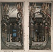
Sorry to make this so long but comments are helping. First the house panels, 1997 GE. four load wires go through the back of the meter panel, through exterior wall, and through the back of the right 200a panel's lower left corner. One pair to the right main and the other pair through the stud to the left panel's main. Neutral in through a mounting hole in the left panel and jumped to the right panel. Both white and copper wires going to the neutral bars Not sure where it starts but an insulated wire comes out at the bottom of the brick exterior and attaches to a buried rod. Blue tape on unused breakers, 10awg wire for tank less hwh's that grew old and new code specified 8 & 6awg wiring.

P HOUSE CB PANELS 3x3.jpg

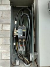
The 200a disconnect installed 2019. Small Cat cable at the bottom used to extend wifi while trench was open and crew laying conduit. Later solar pre inspection said it shouldn't share an electrical enclosure. Three wires in from the adjacent meter and four out,

P SD 200A 3x4.jpg

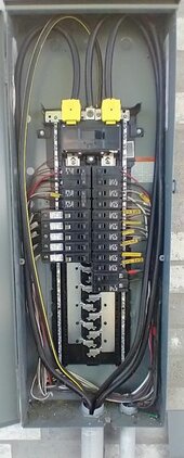
And those four wires surface at the 200a panel at the end of the addition. Green screw out and three, not four, wires out to the shop's 100a panel. Load wires connected to the lower right pair of 100a breakers, That conduit probably too small for heavier wires plus it joins the old conduit rather than a more direct route. A half day rental for a trencher for a more direct run with only an oak tree to get around, or through roots.

ADDITION 200A 3X4.jpg


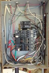
OK, last is the 1987 100a shop panel after I cleaned it up a bit. Ugly but works, someone changed main to 125a but box labeled 100a I added a ground bar, connected the bare wire going through the floor, and separated ground and neutral. Originally a 50x50 metal building, later 10' addition added to the west side and encapsulated the ground wire, hiding what it goes to. I pulled the old apartment 240v hwh and hvac leaving a 60a double without a job. Using it for a 9500W generator I bought after the Texas Freeze' rolling blackouts. Should be enough to support the addition after disconnecting from the main. Red wire nuts on the 8awg wire to the old hvac. Enough for the inverter AC out?
100A PANEL 3x4.jpg

So all that is what I am trying to make work for 38-48 AC amps out.
 
I would like to put Polaris tap on those wires going to 125A breaker in 100A box, branch to another box as PV combiner. Maybe 70A box with 60A PV breaker, no loads.
 
Inverter AC out to a tap on the 100a line to the 200a main panel's breakers, does the 120% 40a limit go away? Is changing the 200a main to 175a easier?

The 100a panel is being replaced, perhaps become a one breaker combiner/pass through. A hom3060L225 arrived today and I have a QO225vh breaker. Does that eliminate the need for a tap and combiner, or would a 150a or 175a be better?
 
I would avoid taps but that's just my own predilection because they involve considerations I'm not familiar with. Easier in my mind to just stick with single circuits and obey the 120% rules.
 
Inverter AC out to a tap on the 100a line to the 200a main panel's breakers, does the 120% 40a limit go away?
Yes but you'll need a combiner box because the inverter can't go straight into the tap without a breaker in between, and you may need to upsize one side of the tap per 705.12(A) math.
Is changing the 200a main to 175a easier?
If the 175A breaker size exists and there is a disconnect before that one, it's not that hard.

If there is no disconnect and this is directly on the meter lug, it depends on whether your POCO allows you to pull the meter. If not then you have to do a disconnect/reconnect dance with them.
The 100a panel is being replaced, perhaps become a one breaker combiner/pass through. A hom3060L225 arrived today and I have a QO225vh breaker. Does that eliminate the need for a tap and combiner, or would a 150a or 175a be better?
I don't understand where this 225A panel is going in in your diagram. If it's replacing the 100A panel it's more compact to just add a backfeed breaker. There's a ton of capacity on that bus for 120% rule.
 
Inverter AC out to a tap on the 100a line to the 200a main panel's breakers, does the 120% 40a limit go away?

I only meant that to not be limited to 120% rule for 100A panel (20A breaker, 16A continuous, if main breaker is 100A.

Doesn't help upstream panels.

Is changing the 200a main to 175a easier?

You do need to address that panel.
I thought 120% was applied based on the backfed breaker (which supplies 100A panel) but maybe these days it is based on the actual PV breaker downstream. I don't read it that way, although it obviously works that way in terms of current.

The 100a panel is being replaced, perhaps become a one breaker combiner/pass through. A hom3060L225 arrived today and I have a QO225vh breaker. Does that eliminate the need for a tap and combiner, or would a 150a or 175a be better?

Right. Replacing it takes care of 120% rule for that panel.
 
Tempting to swap the 225 amp main with the 200 amp main breaker, but NEC probably frowns on that. Changing the 200 amp main to 175 amp main should be OK and pass the calculation rules. Swapping enclosures is more than I want to do. The addition doesn't use many amps so a 175 amp should work and the disconnect provides safety.

Eventually want to upgrade the shop's 100 amp feed. Nassau Cable shows 2-0 ALU URD, direct burial as 263 amps single wire, 233 amps for 2-0/2-0/1 combination. Most wire charts show 2/0 ALU limited to 175 amps, does direct burial allow the higher amperage?

Would a 150 amp main be a better replacement, for the 200 amp main, than the 175?
 
Last edited:
Back
Top