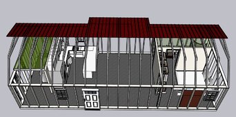
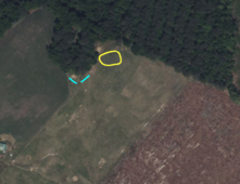
Daughter wants to move back from the big city and wants a tiny house. We've identified a spot near a pond that is about 1000' from our house. I want to run her 16x40' house with 6000xp inverter but it will require load management. I will swap her water heater elements for 1500w elements and replace the lower thermostat with an upper type t-stat. That way when the water heater is satisfied, I can power the EVSE off the bottom thermostat.
First there's peak demand to deal with. For this I will use a passive current sensing switch on each of the two 120v lines. If it trips over 50% capacity, I'll load shed the water heater and EV for 5 minutes. This will give time for things like the oven to dutycycle and thus prevent rapid cycling. I don't think i'll need to load shed the minisplits as I expect they'll draw 170-200w each most of the time when running.
The next issue is low SoC load shedding. I plan to TRY to run her off two 15kwh batteries, but realistically I think she'll need 45kwh because he car will use about 25kwh a day back and forth to work. I've got to create a protocol converter from victron smart shunt to canbus anyway, so I'll add some digital outs on that to inhibit the car charging below something like 30%.
I plan to program the inverter to assert a digital output for gen start at 20% and shut off at 29%. But I'm not going to use a generator. I want to make a small power supply like the sig solar chargeverter... a 1 or 2kw 48v charger. I looked at getting 10amps @ 240v lifeline from our house but it would take AWG4 for the nearly 1000' run. So I've decided to get some 2kva step transformers from ebay. I can step up 240v to 600v, run the distance and step back to 240v on the far end. Using 600v allows me to use AWG12 and I can get 12/2 UF in 1000' spools. So when the inverter calls for gen start, it's actually going to turn on a contactor for that 48v DC charger.
I'll post more about the structure in a few moments.... I hope this is food for thought and please let me know if you have anything to add that I've missed.
Last edited: