diy solar

diy solar

RV 48V to power 12v Loads

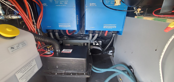
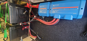
I think there may be some confusion with what my particular setup is in this thread, and what I am doing, so I took some pictures.

I am fulltime in a 5th wheel camper.
The batteries and Lynx Shunt + Lynx Distributor are LiFePO4 300ah at 48vdc+-. These are in a heated bay
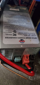
The grey box is the stock converter that I will be removing.
The black box with a black hose out the top is a 12v deep cycle FLA marine/RV battery. This bay with the Quattros is exposed to the outside, i.e. -40f to 120f
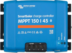
I will be installing this new MPPT right next to the 12v battery. Two 3ft+- 6awg from 12v battery to "Battery" connection on the MPPT. Running two 10ft+- 6awg wires from the lynx distributor to the "PV" on the MPPT.
1714687771218.png1714687725913.png1714687674909.png1714687646183.png
 
Is there a reason why you chose 150/45 instead of cheaper 100/50? Future repurpose as 48V solar MPPT?
 
Is there a reason why you chose 150/45 instead of cheaper 100/50? Future repurpose as 48V solar MPPT?
Yeah, just picked that one for future-proofing, I can use it for panels... If it works good maybe I buy two 100/50s for the job, or one 150/60 or 150/70 ect ect...
The 100/50s only do 12v and 24v systems
 
I mentioned before, I would rather use an actual 100amp 48v to 12v CHARGER, but there seems to be nothing on the market.
 
Sounds like you are describing different concept using isolated battery charger to charge single LFP cell that lags behind other cells in series stack. The charger in that scenario only sees load current of both LFP cell and series current limiting resistor. Charger supplies whatever voltage it set to.
I think you're right. I'm just curious how people are reporting using a charger meant for 12V on a 24V by using a current limiting resistor... I think what you're implying is the charger is completely manual and doesn't try to "sense" the voltage to charge at.

Not to derail the thread... But since you seem to know quite a bit, I'm curious if you've ever seen someone use a 12v/24v 30amp charge controller with a 24v-12v step down converter? (To a 12V battery bank) If the step down converter was rated for the 30amps at 24v would the charge controller see 24v battery from the converter if placed on the charge circuit? If it did... Wouldn't this effectively double the charge capacity for less $$$ than a new MPPT at 12V 50amps?
 
I think you're right. I'm just curious how people are reporting using a charger meant for 12V on a 24V by using a current limiting resistor... I think what you're implying is the charger is completely manual and doesn't try to "sense" the voltage to charge at.

Not to derail the thread... But since you seem to know quite a bit, I'm curious if you've ever seen someone use a 12v/24v 30amp charge controller with a 24v-12v step down converter? If the step down converter was rated for the 30amps at 24v would the charge controller see 24v battery from the converter if placed on the charge circuit? If it did... Wouldn't this effectively double the charge capacity for less $$$ than a new MPPT at 12V 50amps?
Slightly off topic, but it is somewhat relevant. I'm not sure about other brands, but victron mppt need 5v or more, higher the battery it's charging. i.e. 14.6v charging for battery, u need 19.6v on the input or higher. So it seems to be a semi-allowed use-case to have a dc-dc converter powering the PV side of the MPPT. They have limits of how much power the MPPT can have coming in basically how much you can "overpanel" the MPPT. This is what we are discussing, because the setup I am doing is basically limited by the BMS in the batteries, or the fuses...
 
Just make sure to include 20A fuse on PV input and precharge resistor.
I just ordered a blue sea 5191 fuse block terminal and a 30amp terminal fuse for the Lynx Distributor side, and a 60amp for the 12v side. Do i really need to precharge if I hook up the 12v side first? I have a 48v light bulb that I use to precharge my quattros
 
It might be much easier to add a 12V LiFePO4 battery and be done with it 🤔

I have 24vdc>12vdc and it's not ideal. It works OK, gives off some noise, so I just plug my Antron 14vdc supply into AC to run my 7300. It's so little power on receive that the efficiency losses are very small. If you transmit a lot, that could be more problematic. That enables me to always have a backup supply to run my rig.

With the AC>14vdc supply there is no need to run long cables for the DC which was causing a voltage drop and dimming lights on full power.
 
Last edited:
Slightly off topic, but it is somewhat relevant. I'm not sure about other brands, but victron mppt need 5v or more, higher the battery it's charging. i.e. 14.6v charging for battery, u need 19.6v on the input or higher. So it seems to be a semi-allowed use-case to have a dc-dc converter powering the PV side of the MPPT. They have limits of how much power the MPPT can have coming in basically how much you can "overpanel" the MPPT. This is what we are discussing, because the setup I am doing is basically limited by the BMS in the batteries, or the fuses...
That's what has me curious... If I rewired a 12V 200ah lifepo4 to be a 24V 100ah, which would set the charge controller to 24V mode; if it's possible to feed 14.2V from a DC-DC converter in to the PV side when the panels aren't getting sun using a switch, if that charge controller would take the 14.2V 20amps from the DC-DC and actually charge the 24V battery at ~300watts
 
I have a 48v light bulb that I use to precharge my quattros
That should work. Connecting 12V side first does not remove the need for precharge on PV input. I don't know how Victron has PV reverse current blocking implemented. That circuit may not survive inrush current from 48V battery over #6 wire. I suggest using smallest fuse you can get away with in PV input for least amount of fault current during short. I would use 15A ultra fast blow fuse and limit output current to prevent input ever going above 14A. Also placing 0.1 ohm 50 watt resistor in series with input side is a good idea to limit destructive fault current while only wasting 20 watts out of 660 watts going in. But if MPPT never faults then you will not need this protection. But precharge is mandatory in my opinion.
 
That should work. Connecting 12V side first does not remove the need for precharge on PV input. I don't know how Victron has PV reverse current blocking implemented. That circuit may not survive inrush current from 48V battery over #6 wire. I suggest using smallest fuse you can get away with in PV input for least amount of fault current during short. I would use 15A ultra fast blow fuse and limit output current to prevent input ever going above 14A. Also placing 0.1 ohm 50 watt resistor in series with input side is a good idea to limit destructive fault current while only wasting 20 watts out of 660 watts going in. But if MPPT never faults then you will not need this protection. But precharge is mandatory in my opinion.
Edit: nvm. I'm making some coffee
 
That should work. Connecting 12V side first does not remove the need for precharge on PV input. I don't know how Victron has PV reverse current blocking implemented. That circuit may not survive inrush current from 48V battery over #6 wire. I suggest using smallest fuse you can get away with in PV input for least amount of fault current during short. I would use 15A ultra fast blow fuse and limit output current to prevent input ever going above 14A. Also placing 0.1 ohm 50 watt resistor in series with input side is a good idea to limit destructive fault current while only wasting 20 watts out of 660 watts going in. But if MPPT never faults then you will not need this protection. But precharge is mandatory in my opinion.
Okay I think I have a pretty good grasp on the situation. With this system, bolting strait onto the Lynx Distributor with that terminal fuse block is the route I chose for now, 30amp being the smallest terminal fuse I could find. The smallest mega fuses I seem to find are 60amp. I could add something like a 15amp in-line fuse, but this is more of a "trial by fire" / "proof of concept" situation. It's a double edge sword too, smaller fuse = more heat buildup. Realistically this MPPT is too small for my application and should be doubled up, or just get a bigger one, in that case, the 30amp should be about right on the 48v side.
I dont really want to wire in a resistor (again heat), but is there a reputable product on amazon or something that is just like and inline automatic precharger I could use?


As of right now I will install it when it gets here on sunday, hook up the 12v side, get the 48v side ready, use my 48v light bulb to pre-charge, then hook it up. Should be fine right?
 
As of right now I will install it when it gets here on sunday, hook up the 12v side, get the 48v side ready, use my 48v light bulb to pre-charge, then hook it up. Should be fine right?
If this was cheap 75/15 model same that I been using this way I would say yes. But since this is different more expensive MPPT I would take precaution with additional current limiting for first time turn on. That resistor is $3 (plus heatsink) and pack of 20A fuses is $5 (plus fuse holder).
but is there a reputable product on amazon or something that is just like and inline automatic precharger I could use?
Not that I know of.
 
If this was cheap 75/15 model same that I been using this way I would say yes. But since this is different more expensive MPPT I would take precaution with additional current limiting for first time turn on. That resistor is $3 (plus heatsink) and pack of 20A fuses is $5 (plus fuse holder).

Not that I know of.
Awesome, I appreciate the help. Expensive is all relative I guess, I talked myself out of getting another 250/100 VE.Can, or a 250/85 VE.Can for this lil project. If it does work good, it seems like a pair of 100/50 bluesolar might be perfect. Or just grab a second 150/45.
I order this resistor, looks right? Will get here by Sunday: https://www.amazon.com/Pieces-Aluminum-Housed-WireWound-Resistor/dp/B0C7458DPM/

If this works, it will be way cheaper and more efficient vs getting two 48-12/30 converters feeding two 12-12/30 charger or a 12-12/50 charger (which is what the victron dealer suggested) (About $880 plus tax) ($240 per 12-12/30, and $200 per 48-12/30)
 
I'd put in a 12V battery and a step down from 48 to that battery. Run loads of battery.
 
That should work. Connecting 12V side first does not remove the need for precharge on PV input. I don't know how Victron has PV reverse current blocking implemented. That circuit may not survive inrush current from 48V battery over #6 wire. I suggest using smallest fuse you can get away with in PV input for least amount of fault current during short. I would use 15A ultra fast blow fuse and limit output current to prevent input ever going above 14A. Also placing 0.1 ohm 50 watt resistor in series with input side is a good idea to limit destructive fault current while only wasting 20 watts out of 660 watts going in. But if MPPT never faults then you will not need this protection. But precharge is mandatory in my opinion.
With a 30amp charge controller running off a 100V 600watt series string (double it's load capacity) would it be wise to use one of those cheaper circuit breakers rated for 100V-120V DC at say 10amps?

Then maybe a 3-mode battery switch placed after the high voltage circuit breaker to precharge the solar charge controller PV input?

The reason I'm asking is because I tried to fuse my overpaneled SCC with a 600 watt auto reset circuit breaker, but the circuit breaker itself was only rated for 48V max. When I pressed the manual break switch to cut the power, the 87V from the panels arced across the switch and burnt it out.

I ended up having to remove it from the circuit and just wire directly to the SCC PV input from the junction box, with the positive mc4 disconnected on the roof.

This is the breaker I have in mind:
12V-110V DC Miniature Circuit Breaker, 15 Amp 2 Pole Battery Breaker Protector for Solar PV System and RV, Thermal Magnetic Trip, DIN Rail Mount, Chtaixi DC Disconnect Switch B15 https://a.co/d/6bjWJXb
 
When I pressed the manual break switch to cut the power, the 87V from the panels arced across the switch and burnt it out.
I don't like those cheap probably not true DC rated breakers.
Then maybe a 3-mode battery switch placed after the high voltage circuit breaker to precharge the solar charge controller PV input?
Something like FilterGuy suggested. Having fool proof one operation precharge/bypass combo switch would be ideal.
 
Last edited:
Did he delete his posts?
 
Ahh OK yeah that's exactly what I had in mind... I have one exactly designed like this for my 1200watt ,12v inverter precharge.

You also recommended a fuse... I'm trying to think how this could be automated because the charge controller could be protected from overpanneling by using a fuse or a circuit breaker...

How about a precharge 3-mode switch feeding a 100volt 8amp circuit breaker? Or at least a 100V 8amp fuse? I like the circuit breaker because it can trip in a short circuit event... But is that redundant with most mppt SCC's?

I guess what you're suggesting is a fuse is more reliable than a breaker, and should be between the 3-mode switch precharge and the solar charge controller. Since fuses are cheap just keep spares on hand and use the 3-mode switch to cut power during maintenance. The fuse would handle any surge currents

It seems hard to find 100V DC fuses... And you suggest a fast blowing one so I came up with these.

BOJACK F5AL125V 5x20 mm 5 A 125 V fuses 0.2x0.78 Inch 5 amp 125 Volt Fast-Blow Glass Fuses(Pack of 10 Pcs) https://a.co/d/6jFGfCb
 
Last edited:
The fuse is only there to try to prevent or reduce catastrophic failure in case MPPT decides to short PV input due to soft fault. With naturally current limited source like the solar panel it can survive this kind of fault without damage. With virtually unlimited current source (10,000 amps) like 52V 300Ah LFP battery bank this kind of fault can make one big bang. I am not a fan of circuit breakers because cheap ones tend to catch fire and expensive ones are overkill and (not sure 100%) may take longer to break fault current vs. small fuse. There is no need for 100Vdc capable fuse here since source battery is only 58V max. Common cheap 250Vac rated fuses will work on 48V DC under certain conditions as I have demonstrated.
 
The fuse is only there to try to prevent or reduce catastrophic failure in case MPPT decides to short PV input due to soft fault. With naturally current limited source like the solar panel it can survive this kind of fault without damage. With virtually unlimited current source (10,000 amps) like 52V 300Ah LFP battery bank this kind of fault can make one big bang. I am not a fan of circuit breakers because cheap ones tend to catch fire and expensive ones are overkill and (not sure 100%) may take longer to break fault current vs. small fuse. There is no need for 100Vdc capable fuse here since source battery is only 58V max. Common cheap 250Vac rated fuses will work on 48V DC under certain conditions as I have demonstrated.
Thank you for clarifying... That makes sense.

If that's the case... Then my original plan before coming on this thread should work for a 12V lifepo4... I'm placing a high current DC normally-open relay between the lifepo4 and the MPPT, and powering the coils with a voltage sensing relay running off the lifepo4 BMS set to disconnect/cut power at high voltage of say 14.3V (above any standard lifepo4 charge algorithm)
 
So far so good... Nothing has blown up *YET*
Victron 150/45 MPPT fed from 48v battery bank charging a 12v interstate 80ah FLA marine/rv battery.


Hooked up the 12v side first, used the little resistor for the first spark then rammed the wire in and bolted down. Set the parameters and 0amp charge current. Hooked up the 48v site with the little resistor for the first bigger spark and rammed the wire in and bolted down. Turned up the amps.
Seems in order and efficiency seems between 95% and 98%, nothing seems hot even at 30 amps continuous.

One interesting observation: The amps dropped to 0 on the MPPT when I used the hydraulic jacks. Similar setup seem to suggest about 150amp draw. Lights went out from battery draw (common), then everything comes back to normal. Might have something to do with the temporary setup, too small of wire, and no good busbar. Hopefully when I get the heavy wiring and big busbars, the MPPT charges at max capacity vs laying down and giving up, but maybe this is just one quirk of a setup like this. If so, I will have to buy a pair of bigger batteries or something to handle the surges.
 

diy solar

diy solar
Back
Top