diy solar

diy solar

Extending CT's

Steve777

Solar Enthusiast
Joined
Oct 23, 2020
Messages
192
I have a somewhat unusual situation in planning out my upgraded system: How to install the inverter's (and other monitoring devices') CT's right after the grid meter location. Problem is this: grid power comes in from the pole to the barn; there is the meter and then a small panel with 200A split phase breakers. There are a few (like 6 or so) barn CBs, and then this panel feeds some 4/0 Al UF line which runs ~150' to another 200A main breaker which is outside the main house and feeds a CB distribution panel in the house. The inverter, and various monitoring devices will be at the basement level of the house. The inverter and all the various monitoring devices would like their CT's placed between the meter and that first 200A breaker, to get an accurate measure of current going to/from the grid. That will likely need about a 160' or more (with obstacles and all) "extension" to do that.

I have read various reports of people doing this sort of thing, but typically over less distance (like <100') using Cat5 or Cat6 outdoor cable. However seems to me that the added resistance of 150' to 200' of 22ga copper wire would throw off the CT measurements. On some devices it may be possible to change the CT parameters to account for this, but not always.

I'd be interested in hearing from folks that have tried this, if/how well it worked for you, and what devices you tried it with. And if there are better ways of doing this, I'm all ears. What do folks think?
 
Does your inverter support using digital comms to collect CT readings via an energy meter?
Have not made a definitive choice on the inverter yet, but all the ones I am considering use CT's, and a couple can take an energy meter too, but I have not paid much attention to the meter as I did not think I needed one.
 
I run my CT's to a Sol-Ark 15k almost 125' over regular Cat5E cable. Sol-Ark said it should be fine so long as you don't run it parallel to any AC lines because of interference. Its been over a year and it works perfect.
 
I run my CT's to a Sol-Ark 15k almost 125' over regular Cat5E cable. Sol-Ark said it should be fine so long as you don't run it parallel to any AC lines because of interference. Its been over a year and it works perfect.
Good to know. Did you just plug the CT's in to the Cat5, or make some other connections?
 
I expect 160 ft of Cat6 cable will handle a CT extension nicely.

Just make sure you use a twisted pair for the signal, the CT leads have to be twisted together or the signal will pick up electrical noise.

Mike C.
 
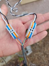
This was how I connected the sensors to the Cat5E cable.
This isn't ideal if I read the picture right.

You want the CT signal to ride on ONE twisted pair. The picture you show implies you combined a pair as one conductor and used two pairs for each CT. That denies the signal of the noise rejection properties of the twisted pair. Your CT signal will more easily pick up electrical noise this way.

I know it seems better to use all the copper in the cable, but your signal integrity will be better if you use only one pair for each CT and leave the other two unused (or ground them at the inverter end).

If you are concerned about the resistance of network cable affecting your results, Cat6 is 23 gauge and you can find cables that are heavier gauge that are twisted pairs. They will be more expensive since network cable is high volume.

Mike C.
 
Couldn't he use a pair of whites and the matching solids for each connection? That way it's still twisted pair but half the resistance of single wires.
 
If your CTs are current mode transformers, then the resistance of the wires doesn’t matter. If they have a burden resistor, then they are voltage mode, and the resistance of the wire may (or may not) make a difference.
 
Couldn't he use a pair of whites and the matching solids for each connection? That way it's still twisted pair but half the resistance of single wires.
Indeed, that would be the best bet. The impedance of the twisted pairs is going to be different, but at 60 Hz it doesn’t matter.
 
Here's me wondering about how a CT will work if I extend the leads 10ft and I've been wondering for nearly 2 years without testing anything....
 
What do folks think?

My 2p worth would be to use an energy meter as @zanydroid mentioned..

With an energy meter you can also do what a few of us have done to implement remote connectivity of RS485 over Ethernet - see my posting here...


and the subsequent discussion on that thread.
 

diy solar

diy solar
Back
Top