diy solar

diy solar

Wireless solution to feed CT clamp data to hybrid inverter

green_graham

New Member
Joined
Sep 10, 2022
Messages
3
Hi all, I've just found the forum whilst trying to research a solution.

I'm looking for some guidance with regards to battery storage.

I have a Luxpower 3.6K hybrid inverter with approx ~3Kwp solar panels.

I'm trying to figure out if it's feasible to DIY adding battery storage (obviously using a qualified electrician for connection).

I'm thinking of adding 3 of these:
https://batteryfactory.co.uk/.../pylon-us5000-4-8kwh-li...

One complication is that the inverter/panels are at the bottom of the garden so a direct CT clamp cable from the grid feed isn't possible.

A bit of research suggests that I should be able to connect the CT clamp to an RS485/MODBUS wireless transmitter/receiver to solve this. I'd appreciate any experiences in this regard and any product recommendations. I do see anything for sale that is a purpose built solution for this. Any links to products and/or homegrown solutions would be appreciated.

If I can't get that wireless link to work, I think I need to bite the bullet and get an additional inverter/charger and locate that and the batteries by the mains feed. This seems like a waste.

What I think I will need to purchase is the following, have I missed anything?
  • 3x battery modules (these come with inter-battery cables)
  • 3x pairs of battery brackets to stack
  • DC isolation switch
  • RS485 wireless transceiver
  • 2x long cables to/from inverter
Is that all there is to it?
 
Hi all, I've just found the forum whilst trying to research a solution.

I'm looking for some guidance with regards to battery storage.

I have a Luxpower 3.6K hybrid inverter with approx ~3Kwp solar panels.

I'm trying to figure out if it's feasible to DIY adding battery storage (obviously using a qualified electrician for connection).

I'm thinking of adding 3 of these:
https://batteryfactory.co.uk/.../pylon-us5000-4-8kwh-li...

One complication is that the inverter/panels are at the bottom of the garden so a direct CT clamp cable from the grid feed isn't possible.

A bit of research suggests that I should be able to connect the CT clamp to an RS485/MODBUS wireless transmitter/receiver to solve this. I'd appreciate any experiences in this regard and any product recommendations. I do see anything for sale that is a purpose built solution for this. Any links to products and/or homegrown solutions would be appreciated.

If I can't get that wireless link to work, I think I need to bite the bullet and get an additional inverter/charger and locate that and the batteries by the mains feed. This seems like a waste.

What I think I will need to purchase is the following, have I missed anything?
  • 3x battery modules (these come with inter-battery cables)
  • 3x pairs of battery brackets to stack
  • DC isolation switch
  • RS485 wireless transceiver
  • 2x long cables to/from inverter
Is that all there is to it?
Hi, I have a solis 3.6k inverter and fox ess lithium battery (big). However these is all in a workshop alongside the outbuilding fuse board.
The issue is that the ct clamp obviously only monitors the workshop power and I need it on the main grid line in.

So, yes I’m looking for the same solution although I’m a little further on that you are. I have an rs485 transparent wireless link kit. You can configure them as point to point but I have them set to connect to my UniFi wireless network which already has a handful of APs.
So essentially I’m trying to tunnel the serial comms for rs485 over my network. The server side (inverter) has data transmission but the ct clamp I haven’t got talking yet. Likely a cable fault, need to check baud rate etc too

For a uk g98 install its amazing this isn’t more common an ask. Who wants a battery and inverter in their house if they have another option?! And I can’t extend the rs486 cable 200m! Or even get the cable there anyway as I don’t have ducting the whole way.
Thanks for the info.

I've gotten impatient and ordered two of these:

I'm hoping it's just a send and forget from the CT clamp to the inverter. You saying your inverter acts as a rs485 server makes me hopeful this is correct.

If I can get the inverter to recognise the CT clamp feed, I can crack on and order the batteries.

Likewise, I'm amazed this isn't a common thing with off-the-shelf solutions. Surely there are enough folk with impossible (or very awkward) setups for a physical cable?
 
CT sensors used in power flow management need accurate voltage-current phase relationship. Although not impossible, packet based communication may not maintain the phasing information accurately enough.
My research so far is that this data feed is MODBUS over RS485. Do you have any more detail of the protocol used by inverters?
 
CT sensors used in power flow management need accurate voltage-current phase relationship. Although not impossible, packet based communication may not maintain the phasing information accurately enough.
My understanding is that the CT sensor is indeed sensitive to the length of the cable - impedance issues etc. Therefore there's a max length, however we're not talking about the CT sensor cable here (or at least i'm not) i'm referring to the link between the energy meter (Acrel acr10r) which the CT plugs in to. This has an RS486 out, in the form of an ethernet cable (only 2 pins used). This meter links to the inverter using RS486 protocol, well technically I believe it's a standard.
Yes MODBUS over RS485 is what I deduced too.
 
Thanks for the info.

I've gotten impatient and ordered two of these:

I'm hoping it's just a send and forget from the CT clamp to the inverter. You saying your inverter acts as a rs485 server makes me hopeful this is correct.

If I can get the inverter to recognise the CT clamp feed, I can crack on and order the batteries.

Likewise, I'm amazed this isn't a common thing with off-the-shelf solutions. Surely there are enough folk with impossible (or very awkward) setups for a physical cable?
I'm playing around with two of these: USR-W610 | USR IOT
 
Maybe you have a solution by now, but if not:-
a) could bury some cat5 cable between house and outbuilding (could use swa cable instead of duct) to transmit the RS485 modbus requests
b) do you have lan / wifi between house and outbuilding, if so send RS485 over ethernet and then via your lan/wifi

Bear in mind that if you need to implement G100 export limitation, the connection must not be wireless.
 
I came across this thread via a google search, I have the same problem in that my PV array and Inverter will be in/on a large detached garage so the export meter will need to be remote from the inverter. The garage was wired for mains when it was built but theres no easy way to run additional cables back to the house without digging up the garden. There is also the fact that whilst the power meter has a 3 wire RS485 connection the inverter only has a 2 wire, so I'm concerned even if I did run a cable I may well run into common mode voltage problems due to differently referenced and unknown grounds at each end.

Treveansalt/green_graham - If either of you got the ISR-W610 or the Lora Wireless modems working I'd be very interested to hear about it, but in the meantime I'll press on and will post here if I'm successful.

My setup is a Solis Hybrid inverter(RHI-3.6k-48ES-5G) that came supplied with an Eastron SDM120CT power meter, so the protocol used will be MODBUS RTU. At the moment I'm toying with using an ethernet powerline adaptor as the point to point link with an RS485 to ethernet converter at each end, as this keeps it off Wifi.
 
... At the moment I'm toying with using an ethernet powerline adaptor as the point to point link with an RS485 to ethernet converter at each end, as this keeps it off Wifi.

Welcome Steve... that is the exact configuration I am using - Solis -> Waveshare RS485 to ethernet -> power line -> power line -> ethernet to RS485 -> power meter (Acrel in my case). Works a treat to remote workshop with separate TT earth.
 
Welcome Steve... that is the exact configuration I am using - Solis -> Waveshare RS485 to ethernet -> power line -> power line -> ethernet to RS485 -> power meter (Acrel in my case). Works a treat to remote workshop with separate TT earth.
Thanks for the quick response and welcome. Could I ask if you kept your ethernet link via powerline completely separate from any existing internet connected hub etc? I was hoping to go point to point and keep this comptely seperate from my home hub/wifi/internet etc but was wondering how easy the Waveshares would be to setup manual IP addresses etc with no DCHP to take care of this.

I'd seen a RS485 to ethernet adaptor called "USR-TCP232-304" and managed to find a pdf of how to setup a point to point link, but I'd definitely prefer to stick to hardware thats been proven to work with an actual inverter/power meter setup thats close to mine.
 
Hi all & following this thread with interest.

Like many of you, I have a situation where I can’t install a hybrid inverter near the incoming mains supply (it will be about 20 meters away). The route I want to take is with the Victron MultiPlus-II GX but as far as I can understand from their technical data the CT sensor appears to be a passive analogue device with a rather short 1m max distance from the inverter.

Although I’m comfortable with electronics I’m a bit of a noob in the solar/battery/inverter space and I’m getting confused. From your conversations it looks like you have chosen inverters that support RS485-based active CT sensors, whereas the one I was hoping to buy is old-school analogue. Am I mis-understanding, or have I simply backed the wrong horse with Victron?

If there is a way of extending it, I do have wired and Wi-Fi LAN fairly close in both locations.

Thanks for your guidance!
 
We're using these.. https://thepihut.com/products/industrial-serial-server-rs485-to-rj45-ethernet with the DIN mount 12V PSU. Ours are connected to the house LAN on their own static IP address. They work equally well, connected point to point, once configured with a static IP address.
Thanks Seagal, after some googling I found the only option was the DIN mount ones, couldnt find a source for the black box variant. Found a nice 12V DIN PSU on CPC Farnell and ordered some Wylex 4way boxes to house it all in. The 2x Waveshares RS485 to ethernet arrived today along with a USB to 485 waveshare so I can test out the power meter responses before going anywhere near the inverter. Thanks for your help. I'll update here with progress.
 
Hi all & following this thread with interest.

Like many of you, I have a situation where I can’t install a hybrid inverter near the incoming mains supply (it will be about 20 meters away). The route I want to take is with the Victron MultiPlus-II GX but as far as I can understand from their technical data the CT sensor appears to be a passive analogue device with a rather short 1m max distance from the inverter.

Although I’m comfortable with electronics I’m a bit of a noob in the solar/battery/inverter space and I’m getting confused. From your conversations it looks like you have chosen inverters that support RS485-based active CT sensors, whereas the one I was hoping to buy is old-school analogue. Am I mis-understanding, or have I simply backed the wrong horse with Victron?

If there is a way of extending it, I do have wired and Wi-Fi LAN fairly close in both locations.

Thanks for your guidance!

The Solis inverter indeed has a dedicated connector for an rs485 connection to a power meter, and comes supplied with said power meter (either Accrel or Eastron) and a CT clamp that goes to the meter.

I had a quick look at the Victron and found a diagram at the top of this page which is what you might need?


The long connection is something called VEBus on an RJ45 to something called a "GX device" with a short RS485 run to the power meter itself. Not sure whether VEBus is an ethernet standard and if it is, can support a LAN connection, but if its ethernet and has to be point to point you could potentially follow a similar route with just a single ethernet to RS485 converter. Worst case, you could mount the GX device close to the inverter and then use the Rs485 -> ethernet powerline -> RS485 being talked about here.
 
Last edited:
The Solis inverter indeed has a dedicated connector for an rs485 connection to a power meter, and comes supplied with said power meter (either Accrel or Eastron) and a CT clamp that goes to the meter.

I had a quick look at the Victron and found a diagram at the top of this page which is what you might need?


The long connection is something called VEBus on an RJ45 to something called a "GX device" with a short RS485 run to the power meter itself. Not sure whether VEBus is an ethernet standard and if it is, can support a LAN connection, but if its ethernet and has to be point to point you could potentially follow a similar route with just a single ethernet to RS485 converter. Worst case, you could mount the GX device close to the inverter and then use the Rs485 -> ethernet powerline -> RS485 being talked about here.
Thanks Steve, Yes I had actually spotted that and should have mendioned in my original post. I understand that energy meter is a hard-wired-in device (not a CT clamp), which adds a further level of complexity I'd rather avoid. Victron are pretty good with the documentation they publish but it just doesn't seem to answer my point. I'll have a look at some of the others including Solis.
 
...I have a situation where I can’t install a hybrid inverter near the incoming mains supply (it will be about 20 meters away). The route I want to take is with the Victron MultiPlus-II GX but as far as I can understand from their technical data the CT sensor appears to be a passive analogue device with a rather short 1m max distance from the inverter.
...

If there is a way of extending it, I do have wired and Wi-Fi LAN fairly close in both locations.

Thanks for your guidance!

IMHO 20m isn't that far ?‍♀️... As it's a current clamp, should be able to extend that distance with twisted or screened cable.

See also this article from the emonPi people...


Guess the only issue is that if you have problems, Victron won't help.
 
Thanks Seagal, after some googling I found the only option was the DIN mount ones, couldnt find a source for the black box variant. Found a nice 12V DIN PSU on CPC Farnell and ordered some Wylex 4way boxes to house it all in. The 2x Waveshares RS485 to ethernet arrived today along with a USB to 485 waveshare so I can test out the power meter responses before going anywhere near the inverter. Thanks for your help. I'll update here with progress.

Update: A Modbus program on my PC via a USB to RS485 converter can now talk to the Eastron SDM120CT Power Meter over an ethernet powerline connection. Although it took around 3 hours to get up and running the only reason it took that long was a misconnected RS485 wire - grrr!

The software setup of the two waveshares was straightfoward which I did on my Lan fist but using static IP, TCPServer at the power meter end and TCPClient at the inverter end, I didn't seem to need any of the fancy Modbus TCP to RDU protocol settings. When I transferred over to the powerline adaptors no mods were needed and it connected first time.

I now need to install the PSU/Waveshare/power meter setup next to the consumer unit and wire it in for power, then I'll connect the other end to my Solis inverter and fingers crossed that will be me up and running. Will update when fully complete.

All successfully completed.

Inverter -> RS485 to ethernet converter -> Powerline adaptor -> mains cable -> Powerline adaptor -> ethernet/RS485 converter -> Power meter with CT.

Inverter (Solis 3.6kW Hybrid RHI-3.6k-48ES-5G) end:

IMG20221124122114 (002).jpg

and the power meter (SDM120CTM) / incoming mains end:

IMG20221124132013 (002).jpg

.......showing 0W consumption.

The distance between inverter and power meter is some 30m, as the inverter/PV is in/on a detached garage at the bottom of the garden.

The ethernet powerline adaptors are both out of shot, but were two I had were supplied with a YouView box that I'd never needed. (TP-Link). I didnt bother trying to put them on the same circuit and they connect just fine. At 9600 baud with a few bytes of transaction every second or so I can't imagine latency/bandwidth would be an issue.

Detail for those who come across this via googling:

2x Waveshares from amazon:
https://www.amazon.co.uk/gp/product/B09QMNWYLQ/ref=ppx_yo_dt_b_asin_title_o03_s00?ie=UTF8&psc=1

but also available from PiHut:
https://thepihut.com/products/industrial-serial-server-rs485-to-rj45-ethernet

2x housings are Wylex ESE4s (4 modules) and whilst that worked well for the inverter end I'd recommend something bigger for the power meter end as there is no space between the DIN modules and the box sides for wires. I had to cut away some of the DIN rail to make room for wire connections from top to bottom (12V power, and mains needs to feed both power meter and PSU) which was less than ideal.

DIN PSUs from CPC-Farnell:
https://cpc.farnell.com/ideal-power...-12v-1-25a-15w-ac/dp/PW04977?CMP=TREML007-005

As said before the Waveshare setup was quite simple:

- Assign a static IP at both ends (I used 192.168.0.200 and 192.168.0.201)
- Set one Waveshare to TCP server (power meter end) and the other to TCP Client (inverter end)
- Set 9600 baud, no parity, 1 stop bit to match the Solis and SDM120.
- I just left protocol set to "None" as it worked. There is a Modbus TCP to RTU setting which may improve performance/avoid locking up ethernet traffic on a LAN but as mine was point to point via its own powerline I just stopped there and never tested it.

I set the Waveshares up using Vircom (see the Wiki here https://www.waveshare.com/wiki/RS485_TO_ETH_(B)) plugging both ends into a router . I then tested the complete link using a Modbus program (https://www.modbustools.com/quickstart.html) with an additional USB to RS485 converter connected to my PC at the inverter side to check I could get responses out of my power meter before then connecting it all up in situ.

As there was basically no customisation required I couldn't see why this solution wouldn't work for any inverter to power meter connection utilising RS485. There has to be a mains connection between the two, so using that as the comms link is the obvious choice.
 
Last edited:
All successfully completed.

Inverter -> RS485 to ethernet converter -> Powerline adaptor -> mains cable -> Powerline adaptor -> ethernet/RS485 converter -> Power meter with CT.

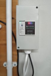
Inverter (Solis 3.6kW Hybrid RHI-3.6k-48ES-5G) end:

View attachment 121686

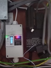
and the power meter (SDM120CTM) / incoming mains end:

View attachment 121687

.......showing 0W consumption.

The distance between inverter and power meter is some 30m, as the inverter/PV is in/on a detached garage at the bottom of the garden.

The ethernet powerline adaptors are both out of shot, but were two I had were supplied with a YouView box that I'd never needed. (TP-Link). I didnt bother trying to put them on the same circuit and they connect just fine. At 9600 baud with a few bytes of transaction every second or so I can't imagine latency/bandwidth would be an issue.

Detail for those who come across this via googling:

2x Waveshares from amazon:
https://www.amazon.co.uk/gp/product/B09QMNWYLQ/ref=ppx_yo_dt_b_asin_title_o03_s00?ie=UTF8&psc=1

but also available from PiHut:
https://thepihut.com/products/industrial-serial-server-rs485-to-rj45-ethernet

2x housings are Wylex ESE4s (4 modules) and whilst that worked well for the inverter end I'd recommend something bigger for the power meter end as there is no space between the DIN modules and the box sides for wires. I had to cut away some of the DIN rail to make room for wire connections from top to bottom (12V power, and mains needs to feed both power meter and PSU) which was less than ideal.

DIN PSUs from CPC-Farnell:
https://cpc.farnell.com/ideal-power...-12v-1-25a-15w-ac/dp/PW04977?CMP=TREML007-005

As said before the Waveshare setup was quite simple:

- Assign a static IP at both ends (I used 192.168.0.200 and 192.168.0.201)
- Set one Waveshare to TCP server (power meter end) and the other to TCP Client (inverter end)
- Set 9600 baud, no parity, 1 stop bit to match the Solis and SDM120.
- I just left protocol set to "None" as it worked. There is a Modbus TCP to RTU setting which may improve performance/avoid locking up ethernet traffic on a LAN but as mine was point to point via its own powerline I just stopped there and never tested it.

I set the Waveshares up using Vircom (see the Wiki here https://www.waveshare.com/wiki/RS485_TO_ETH_(B)) plugging both ends into a router . I then tested the complete link using a Modbus program (https://www.modbustools.com/quickstart.html) with an additional USB to RS485 converter connected to my PC at the inverter side to check I could get responses out of my power meter before then connecting it all up in situ.

As there was basically no customisation required I couldn't see why this solution wouldn't work for any inverter to power meter connection utilising RS485. There has to be a mains connection between the two, so using that as the comms link is the obvious choice.
Thank you, Steve. This is very useful and almost exactly what I plan to do.
The difference in my case is that I plan to use my wired LAN at both ends and also the PoE (also available at both ends) version of the Waveshares. I'll report back in a few weeks once complete.
 
@Swaff I researched this only the other day, I'm using a Quattro 48/10000, and I've diverted (well the electrician will connect it) the incoming mains via my detached garage, this involved running two circa 20 meter lengths of 25mm SWA.

I don't need an energy meter on the incoming mains, as everything will pass through the Quattro. But I have a separate PV array on the house, and for monitoring purposes the Victron system needs to know what it's producing.

I've ordered an ET112 energy meter, and RS485 usb adapter, the adaptor will be extended with CAT6 cable, which my research shows will be more than adequate for such a relatively short extension. The meter will be installed between the generation meter and consumer unit.

You can get ZigBee RS485 wireless adaptors, but using network cable is cheaper, and should be more reliable.
 
You can get ZigBee RS485 wireless adaptors, but using network cable is cheaper, and should be more reliable.
Yes, more reliable and also, if you ever need G100 compliance in future, the connection has to _not_ be wireless.
 
OK, so I thought I’d report back just in case it is if any use to someone planning something similar in the future. I finally got around to completing [most] of my project over the Christmas holidays it was fun and it’s been running well for a couple of weeks now.

It took me a long time to put together but - as is always the case - If I did it again it would go a lot quicker, a lot of learning. The biggest problem I had was a stupid wiring problem that took me a very long time to track down but turned out to be a very simple reversal of the RS485 A & B wires. Grrr.

All of the configuration and other commissioning was surprisingly straightforward.

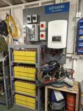
The key components of my system are:
  • Solis RHI-6K-48ES-5G Hybrid inverter
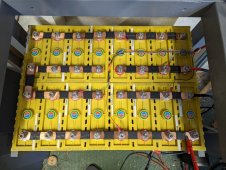
  • A “home brew” 48v 21kWh battery comprised 64 Winston WB-LYP100AHA LiFeYPO4 cells
  • A Seplos 150A BMS
  • Pair of PoE Waveshare RS485-Ethernet extenders.
This is phase 1 of the project where I charge the batteries during the night at £0.10 per unit and then consume it during the day avoiding much higher day rate. I don’t have any PVs attached yet but plan to do so in the coming weeks. That should be a simpler (famous last words!) task.

I don’t plan to document every aspect of the install here but I’m happy to field any questions from people planning something similar.

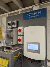
I include some photos just in case they are of use/interest to anyone, the battery "cabinet" has covers.
 

Attachments

  • PXL_20230113_173314989.jpg
    PXL_20230113_173314989.jpg
    223.4 KB · Views: 53
  • PXL_20230113_173446276.jpg
    PXL_20230113_173446276.jpg
    144.2 KB · Views: 43
  • PXL_20230113_173638866.jpg
    PXL_20230113_173638866.jpg
    160.9 KB · Views: 46
  • PXL_20221215_110947346.jpg
    PXL_20221215_110947346.jpg
    306.3 KB · Views: 45

diy solar

diy solar
Back
Top