diy solar

diy solar

Wireless solution to feed CT clamp data to hybrid inverter

Hi.. very interesting read... I plan on following the same setup as @SeaGal and @SteveB123. My question is - is there a compatible wireless version of the WaveShare devices as one side of my setup the wifi powerline adapter is already setup and connected to my router in a different room?

Also.. I picked these devices instead.. I assume they will be ok for reading data from CT clamp and delivering to inverter

Waveshare RS485 to Ethernet Converter Supports Customized Heartbeat/Registration Packets,Webpage,RFC2217-like Protocol Available Client Modes TCP Server, TCP Client, UDP Server, UDP Client, HTTPD https://amzn.eu/d/bz97gIw


Craig,.
 
Last edited:
Hi.. very interesting read... I plan on following the same setup as @SeaGal and @SteveB123. My question is - is there a compatible wireless version of the WaveShare devices as one side of my setup the wifi powerline adapter is already setup and connected to my router in a different room?
Not that I am aware of... so you may need to connect the waveshare device to a wireless access port LAN interface. BUT... if you have power near your meter to power the waveshare and/or wireless device, why not just plug in another powerline adapter? Powerline adapters are not point to point, so you can have a third one on your powerline network.

Also.. I picked these devices instead.. I assume they will be ok for reading data from CT clamp and delivering to inverter

Waveshare RS485 to Ethernet Converter Supports Customized Heartbeat/Registration Packets,Webpage,RFC2217-like Protocol Available Client Modes TCP Server, TCP Client, UDP Server, UDP Client, HTTPD https://amzn.eu/d/bz97gIw
One would assume / hope that the underlying software and functionality of that device would be the same as the industrial one we used.
 
OK, so I thought I’d report back just in case it is if any use to someone planning something similar in the future. I finally got around to completing [most] of my project over the Christmas holidays it was fun and it’s been running well for a couple of weeks now.

It took me a long time to put together but - as is always the case - If I did it again it would go a lot quicker, a lot of learning. The biggest problem I had was a stupid wiring problem that took me a very long time to track down but turned out to be a very simple reversal of the RS485 A & B wires. Grrr.

All of the configuration and other commissioning was surprisingly straightforward.

The key components of my system are:
  • Solis RHI-6K-48ES-5G Hybrid inverter
  • A “home brew” 48v 21kWh battery comprised 64 Winston WB-LYP100AHA LiFeYPO4 cells
  • A Seplos 150A BMS
  • Pair of PoE Waveshare RS485-Ethernet extenders.
This is phase 1 of the project where I charge the batteries during the night at £0.10 per unit and then consume it during the day avoiding much higher day rate. I don’t have any PVs attached yet but plan to do so in the coming weeks. That should be a simpler (famous last words!) task.

I don’t plan to document every aspect of the install here but I’m happy to field any questions from people planning something similar.

I include some photos just in case they are of use/interest to anyone, the battery "cabinet" has covers.
Pleased its all gone well.

For your Seplos BMS, what do you set the battery type to in the inverter? (I have a Nissan Leaf which will be approaching 10 years old in a few years so sussing out some options in advance)
 
Just done exactly this with my setup and it is working beautifully. Great description and easy to follow and many thanks.
Loads of people must need to do this surely.
My next step is to activate the RS485 interface on my SolarEdge 6kW HD Wave PV inverter and link this back to the Solis Hybrid inverter connections and enable the export power limits. Do you foresee any issues?
Regards to you all
Phil
 
My next step is to activate the RS485 interface on my SolarEdge 6kW HD Wave PV inverter and link this back to the Solis Hybrid inverter connections and enable the export power limits. Do you foresee any issues?
Not sure exactly what you mean by the above - can you share a diagram? Note that RS485 is just an electrical specification, it does not define any data protocols passing over it, hence I don't understand what SolarEdge to Solis linking you are attempting to achieve?
 
Oh - thankyou for the reply. Diagram will be tricky, but I will try with words first.

The set up is this:
PV - SolarEdge inverter
Battery - Solis Hybrid inverter.
RS485 connection to the Solis only at the moment and measure the incoming supply for power control. Will not export electricity as it is set.
RS485 connection to SolarEdge not made yet and would like to do this so the PV knows when there is no demand from the house or the battery it will limit production so as not to export anything. I do not sell spare to the grid.
So, I am thinking extend the RS485 wires from the Solis inverter and on to the SolarEdge so SolarEdge also knows what the incoming supply is doing. Importing or Exporting.
Is this clearer?
Was thinking to have a go this weekend and see what happens.
Can have a go at a drawing too if I get time.
Phil
 
So, I am thinking extend the RS485 wires from the Solis inverter and on to the SolarEdge so SolarEdge also knows what the incoming supply is doing. Importing or Exporting.
Unless the SolarEdge talks the same data and protocol, I don't see how that would work.

You _may_ get lucky and find they use the same modbus registers etc, but IMHO would think that is unlikely. You may need to implement a MITM solution like @peufeu is working on.
 
Ping!

My Solis EH1P-6K can charge its batteries from excess solar produced by another inverter in the house, ie when its meter reports power being exported it will absorb it. This only works if the other inverter is set to something other than zero export, otherwise it won't export, so the Solis won't see any export, and it won't do anything. Basically the inverters cannot "know" whether the other inverter has potential untapped production that it could use, unless the other inverter is actually producing that power. It's quite a mess.

Maybe your RHI model can do the same, they're quite similar.

The Solis has to be set to higher than zero export for this to work. If the meter reports exported power higher than what the max export power is set on the solis, it will freak out and shut down. So you can't do zero export with this.

It's not possible to have 2 inverters as masters on the same modbus for the same meter.

If you add a brainbox you can do more stuff but it needs programming.
 
After getting frusted with a few other RS485 link options (including a wireless Lora link), I've just setup the waveshare DIN rail mount RS485 to Eth adapters and they've been working flawlessly. I'm going to put the powermeter side (Server) into an 8 way consumer unit type box with the din mount power supply and the Power Meter too (amazon 8way din rail box). It might squeeze into a 8way box, so I've chosed a fairly tall unit, i'll let you know how I get on.

Essentially though I had zero issues with the setup of the waveshare devices, and for me the easiest config was to just plug them into my home network. Setup a dual IP on my computer to include the relevant subnet and then configure them. What exactly do I mean by this?
The waveshare RS485 to Ethernet devices come out the box with static IP 192.168.1.200, if you're computer IP is already on a 192.168.1.xxx address through DHCP allocation you can just browse ot the default device address: http://192.168.1.200.

I've a few VLANs and a somewhat more complex setup, however in essence on a Windows computer I browsed to 'view network connections' in control panel. Selected the active network > Properties > Internet Protocol Version 4 > Properties > Alternative Configuration >
I entered a random IP on the devices subnet, so something like:

IP: 192.168.1.3
Subnet: 255.255.255.0

Then select ok, and you should be able to browse to device's static & default IP: http://192.168.1.200

Please note, I am using my 'home' network with DHCP running. I could have used powerline adapters to create a 'direct' link, but this provided no benefit to me. Luckily I pulled through ethernet when I re-wired my house many moons ago. Distance between the Meter and Inverter... a long way! Front to back of house + garden workshop with ubiquiti wireless bridge. Obviously this is using my LAN so it's all on structured CAT5e apart from the wireless bridge.

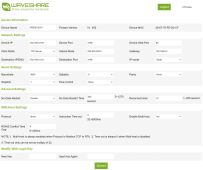
I then configured it like this... (see attachment).

NOTE: just plug ONE waveshare device in to start, otherwise you'll have two on the same IP address. Only plug the second one in once you're configured the first and changed it's IP. Also, make a half decent password and record it safely, capitals, numbers, letters, special characters etc.

An example setup for my network with DHCP configured on 192.168.0.xxx
1. Device IP: 192.168.0.190
Work Mode: TCP Server
Gateway: 192.168.0.2
IP Mode: Static
Destination IP: 192.168.0.191
Baudrate: 9600

Leave other other settings as default.
second device...
2. Device IP: 192.168.0.191
Work Mode: TCP Client
gateway: 192.168.0.2
IP mode: static
Destination IP: 192.168.0.190
baudrate: 9600

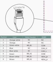
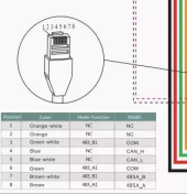
Once this was done, I plugged in the RS485 lines (A & B) to both ends (power meter link into 'Server' Device). Client device into the Solis Inverter.

The link lights flashed and everything worked perfectly.


The only frustration really is that the RS485 cable was for me supplyed with an RJ45 end (Network), I didn't want to destroy that cable so I used a network socket and just used a pair of cables from CAT5 to connect to the two active pins on the socket. I'm sure there's a better way of doing this, but I wanted to keep the stock cables untouched. How have others managed this? I'm sure my way isn't the quickest!


Anyway, I hope that little writeup helps someone out there.
 

Attachments

  • waveshare example.png
    waveshare example.png
    296.2 KB · Views: 49
Glad I found this solution via good old Google, I have a Solis 5G hybrid installation and same issue with all being in a detached garage and the meter being in the middle of the house under the stairs so a cable was not an option, but I have internet to the cabins in the garden etc via the garage which meant this solution was perfect. The initial install went flawlessly and was working great. I should say at this time no battery is connected (that is due to be installed in a couple of months when funds allow) so the inverter shuts down every night. Everything was great but I was getting issues with the app from solis showing some incorrect data. I had a ticket open and whilst away suddenly got a fault message saying comes fail. When I got back sure enough the RS485 was not showing as ok. I tried rebooting the Waveshares no joy, I also noticed that the inverter HMI was now showing the backup output was enabled, not done by me. To cut a long story short I tried everything even reset the inverter (which turns the backup output on, did Solis do a remote reset?) the only way I can get the connection working is to enable the Modbus protocol, and because it currently shuts down at night it needs the no data restart enabled at 60 seconds so in the morning I get an error message as it never comes straight up until the no data restart kicks in on the waveshare. Once I get the battery on this should go away.
 
I was pointed here from someone on a Facebook group, and this setup ended up working perfectly, but I did have a few issues that I'll go through to hopefully help someone in the future...

The in laws had a Solis 3kW string inverter installed in an outbuilding, but decided they absolutely needed a battery (mother-in-laws sister got one)
I was tasked with updating, and saw the opportunity to offload my Solis 3kW hybrid and upgrade myself to a 6kW hybrid, as long as I could sort the meter issue out. I'd already established a powerline ethernet link for the data logging stick, so just needed some way of running RS485 over that. Enter this thread, and the Waveshares...

There was a spare row in the house consumer unit (former off peak half of the board) so the Acrel ACR10R meter, Waveshare and power supply were mounted there. Everything set up and configured per this thread, blue lights, packets being transmitted and received, everything looked good except the inverter said 'RS485 fail' and the 'Com' light on the meter wasn't illuminated or flashing.

After a good few hours of messing about, I found the issue. Despite the markings and the manual, the Acrel ACR10R only seems to want to communicate via the RJ45 socket on pins 3 and 6. I had a load of shielded patch leads around 30cm long left over from a SCADA upgrade at work, but the ends were made off non standard, so pins 3 and 6 were across different pairs on these weird leads. Consequently, I was using pins 1 and 2, which were a pair on my leads, and claimed to be OK on the diagram on the meter itself and the manual. I also tried using just a bit of twisted pair straight into the terminals at the bottom (21 and 22 off the top of my head). Still, no dice. I also tried using pins 3 and 6 despite them being on different pairs, just in case, that didn't work either.

Obviously many hours passed as I was sure it wasn't that, but it was only until I did a continuity test between all the pins that were all supposed to be the same thing I brought myself to cut up a standard patch lead, using pins 3 and 6 which were the same pair, and it all sprung into life. Everything's now working perfectly and I'm awaiting delivery of a Puredrive battery to complete the setup.
 
The only frustration really is that the RS485 cable was for me supplyed with an RJ45 end (Network), I didn't want to destroy that cable so I used a network socket and just used a pair of cables from CAT5 to connect to the two active pins on the socket. I'm sure there's a better way of doing this, but I wanted to keep the stock cables untouched. How have others managed this? I'm sure my way isn't the quickest!
Good write-up... I did exactly the same at the RJ45 end of my Solis cable (y)
 
Direction of AC power flow detection relies on AC phase measurement between AC voltage and AC current.

Putting extra delay in current sensor output signal path can screw up power flow direction sensing.

Inverters with ability to block grid back feed usually limit back feeding when grid incoming current drops below about 3 to 5 amps. This is to allow a margin of error to avoid measurement inaccuracy of CT sensor allowing inverter to produce some grid reverse feed current.

Just a long twisted pair wiring from CT sensor to inverter can cause enough phase error due to parasitic capacitance to impact power flow direction measurement. Since a twisted wire pair has a transmission line impedance of close to 100 ohms, there is often a 100 ohm 'burden' resistor placed in inverter to properly terminate the twisted pair line coming from CT sensor.
 
Hi Folks,

God bless i found this thread. I was trying to achieve the same thing. Unfortunately I already spent a lot of time trying to make it work with EBYTE E32 RF433 transceivers. I'm unable to make it work so far. Meter COM LED just doesn't come up, despite config on E32 being correct. Does anyone have success with with those?

Or i guess I'll go with already tester method via ethernet. I found that there is also Waveshare to Wifi DIN module available.


BTW pinout I'm using from RJ45 to unit are pins 3+7 and 6+8 as per wiring diagram. I've tested it with solis directly connected and it works:
 

Attachments

  • Screenshot 2023-07-18 at 20.42.04.png
    Screenshot 2023-07-18 at 20.42.04.png
    114.2 KB · Views: 13
Or i guess I'll go with already tester method via ethernet. I found that there is also Waveshare to Wifi DIN module available.
Sure. But more expensive and, personally, I'd choose wired rather than WiFi for critical systems any day. Also note that if you ever need G100 compliance, it must be wired, not wireless.
 
Sure. But more expensive and, personally, I'd choose wired rather than WiFi for critical systems any day. Also note that if you ever need G100 compliance, it must be wired, not wireless.
I guess for G100 ethernet cable would not work either.
I'll be doing G98. It is limited in inverter anyway. I'd have to drill a lot of walls to get cable, so no go for me.
I personally don't see a lot of issues with p2p wifi option, latency will be low and in terms of reliability it will be the same as ethernet. I've checked what meter is sending and it is like one or couple messages per second, so it will be fast enough. Latency for power output inside the inverter are like 10x higher than this.
 
Direction of AC power flow detection relies on AC phase measurement between AC voltage and AC current.

Putting extra delay in current sensor output signal path can screw up power flow direction sensing.

Inverters with ability to block grid back feed usually limit back feeding when grid incoming current drops below about 3 to 5 amps. This is to allow a margin of error to avoid measurement inaccuracy of CT sensor allowing inverter to produce some grid reverse feed current.

Just a long twisted pair wiring from CT sensor to inverter can cause enough phase error due to parasitic capacitance to impact power flow direction measurement. Since a twisted wire pair has a transmission line impedance of close to 100 ohms, there is often a 100 ohm 'burden' resistor placed in inverter to properly terminate the twisted pair line coming from CT sensor.
Topic subject line might be misleading here.

Discussion here is not putting stuff between CT clamp as such, it is to transfer already harvested readings for longer distances. There are no alterations between CT and meter, where it is sensetive.

CT=>Meter=>Inverter - in this route we're looking at meter=>inverter link, which even according to many meter manufacturers can be extended as long as required (RS485 Modbus over twisted pair).

What discussed here is introducing tcp/ip for transmitting modbus (either using UTP or wirelessly) CT=>Meter=>Ethernet=>inverter.

Hope this helps.
 
I was pointed here from someone on a Facebook group, and this setup ended up working perfectly, but I did have a few issues that I'll go through to hopefully help someone in the future...

The in laws had a Solis 3kW string inverter installed in an outbuilding, but decided they absolutely needed a battery (mother-in-laws sister got one)
I was tasked with updating, and saw the opportunity to offload my Solis 3kW hybrid and upgrade myself to a 6kW hybrid, as long as I could sort the meter issue out. I'd already established a powerline ethernet link for the data logging stick, so just needed some way of running RS485 over that. Enter this thread, and the Waveshares...

There was a spare row in the house consumer unit (former off peak half of the board) so the Acrel ACR10R meter, Waveshare and power supply were mounted there. Everything set up and configured per this thread, blue lights, packets being transmitted and received, everything looked good except the inverter said 'RS485 fail' and the 'Com' light on the meter wasn't illuminated or flashing.

After a good few hours of messing about, I found the issue. Despite the markings and the manual, the Acrel ACR10R only seems to want to communicate via the RJ45 socket on pins 3 and 6. I had a load of shielded patch leads around 30cm long left over from a SCADA upgrade at work, but the ends were made off non standard, so pins 3 and 6 were across different pairs on these weird leads. Consequently, I was using pins 1 and 2, which were a pair on my leads, and claimed to be OK on the diagram on the meter itself and the manual. I also tried using just a bit of twisted pair straight into the terminals at the bottom (21 and 22 off the top of my head). Still, no dice. I also tried using pins 3 and 6 despite them being on different pairs, just in case, that didn't work either.

Obviously many hours passed as I was sure it wasn't that, but it was only until I did a continuity test between all the pins that were all supposed to be the same thing I brought myself to cut up a standard patch lead, using pins 3 and 6 which were the same pair, and it all sprung into life. Everything's now working perfectly and I'm awaiting delivery of a Puredrive battery to complete the setup.
Could you please confirm which pins you've used for Acrel? I'm a bit struggling to make it work with the ethernet server. For inverter I've used 3+7 and 6+8 and it worked fine with Solis.
 

Attachments

  • Screenshot 2023-07-19 at 18.12.28.png
    Screenshot 2023-07-19 at 18.12.28.png
    486.6 KB · Views: 10
If you are in the Victron world a Shelly 1EM (Wifi) works well (with the added benefit of being able to use a second CT clamp on an EV circuit if you have one)

It does not have the terrible lag that some Victron meters have


Screenshot 2023-07-20 112424.png
 
If you are in the Victron world a Shelly 1EM (Wifi) works well (with the added benefit of being able to use a second CT clamp on an EV circuit if you have one)

It does not have the terrible lag that some Victron meters have


View attachment 158361
Shelly meter is very nice, unfortunately i don't think it will work with my Solis inverter.

I actually found this bridge:

benefit is it is 220v and you don't need additional PSU.

Unfortunately I still can't make stuff work with Acrel, it is just not sending anything to the bridge
 
Could you please confirm which pins you've used for Acrel? I'm a bit struggling to make it work with the ethernet server. For inverter I've used 3+7 and 6+8 and it worked fine with Solis.
From the RJ45 connection on the Acrel connect green to RS485A on the Waveshare adapter and green-white to the RS485B. Common/ground is not required.

BTW: For some reason the individually marked RS485 pins on the Acrel didn't work for me.
 
From the RJ45 connection on the Acrel connect green to RS485A on the Waveshare adapter and green-white to the RS485B. Common/ground is not required.

BTW: For some reason the individually marked RS485 pins on the Acrel didn't work for me.
I'm pretty sure I tried it, going to do it again.
Yeah pins 21/22 do not work at all.

PS. I got another meter - Eastron SDM120CT-Modbus, i hope it works, if so, it will also take less space on a din rail.
 
OK, Got Eastron today, however same issue... really not sure what I'm doing wrong...

it is just doesn't send any data on enternet bridge RS485 port

1689947410659.png


Interestingly if i connect bridge to inverter, inverter actually sending data:
1689947510390.png
there are not many settings to play with really...

1689947552727.png
 

diy solar

diy solar
Back
Top