diy solar

diy solar

Incompatible 100w solar panels? 100w x 4 in series

Looks like its this brand of capacitor: https://www.ymin.com/uploads/files/20210602/a88c8fe5d8070f74c949397515f423f7.pdf

This is the exact replacement: https://www.digikey.com/en/products/detail/rubycon/35ZLH2200MEFC16X25/3564493

I'll go ahead and order 3 and give it a try. I'll replace both 35v capacitors. Second one looks good but I'll replace it just for safety.
Remember the part where the output FET in the MPPT circuitry is shorted, and connects the solar PV inputs directly to the battery? This causes two things to happen:

1) When the battery is connected, the solar panels are connected directly to the battery, and cannot produce more voltage than the battery voltage.

2) When the battery is _NOT_ connected, the solar panel string voltage (80 or 100+ or whatever) is applied directly to the battery terminals, where you have 35V capacitors.

The blown caps aren't the problem, they are the result of the above. Yes, replace the caps, but fix the real problem first, or you'll just blow up the new caps when you connect everything up without the battery.
 
Yea I think it's this. But how could I be over the 100V rating when the Vmax of the panels theoretically could be 97V? I'm thinking now the absolute max the charger can handle is 3 in series, or about 72V.

One interesting behavior is if I connect the solar panels only, without the battery connection, the controller stays on but will ramp up the PV voltage and display something like 67V then it'll just slowly decrease... So it started at 67V and now I'm at 48V and still decreasing... so weird, but the second I reconnect the battery, a small spark with the battery hookup and the voltage for PV drops back down to 13.6V....

Edit: Just checked the controller after it was plugged in this way for awhile. It started smoking and sizzling... definitely something majorly wrong with it....surprisingly it still works...lol I don't trust it any longer. Hopefully I'll get a modest replacement... and definitely never connecting more than 3 panels in series on this one... bummer.
According to all of the manuals I have for my controllers if you connect the panels without a battery it fries the controller. Explains the sizzling and damage.

Example :

WARNING! Connect the battery terminal wires to the charge controller FIRST, then connect the solar panel(s) to the charge controller. NEVER connect solar panel to charge controller before the battery.
 
Last edited:
Yea the guy when I reached out on eBay literally said to do that... I was naive to try that...poor me... Anyway. I haven't been able to find any issue with the mosfets... I'm trying to learn how to test them, it appears there's 4 different kinds of mosfets. So far I'm not really seeing an issue based on my little knowledge. Definitely nothing is burnt out.
 
I have 4 blown mosfets. Two are dead shorted and the other two are completely broken connection and don't have any sort of continuity. I'll try and find replacements now...

Correction: 3 of them are Schottky Barrier Rectifier which are reverse bias, whatever that means. Apparently those are good and will test different than a mosfet. I'm for sure that I have a blown mosfet, model: NCEP039N10M. Apparently there a little difficult to find but I'll try and find an equivalent replacement
 
Last edited:
I have 4 blown mosfets. Two are dead shorted and the other two are completely broken connection and don't have any sort of continuity. I'll try and find replacements now...

Correction: 3 of them are Schottky Barrier Rectifier which are reverse bias, whatever that means. Apparently those are good and will test different than a mosfet. I'm for sure that I have a blown mosfet, model: NCEP039N10M. Apparently there a little difficult to find but I'll try and find an equivalent replacement

If there is not any visible damage

Always simpler to just replace all the silicone on the board and the electrolytic caps at once. Is simpler than troubleshooting most of the time.
 
Out of warranty?

No warranty to speak of. And outside of ebay return policy... Looks like I'll have to try and salvage on my own...my confidence isn't too high...

I've ordered the new mosfet also... caps already shipped so I should have everything hopefully by the end of this week possibly...

Soldered the working mosfets back on the board. My only fear now is I'm not sure if there's a solid state memory chip on board that keeps the firmware intact or if I removed some of these components, it has to reload the firmware...hopefully not but I should know soon enough...

It would be very unusual if the firmware wasn't burned into a chip some place verse in some sort of dynamic memory. Sticking to the mosfets and caps should be safe enough.

Still kinda a wag since FETs seldom blow in isolation - if it was overvolt on the input there may be other damaged components on the input that are harder to test. I'd be inspecting it with a magnifying glass to see if any of the components look like they got hot or cracked or if any of the solder to them looks different to the rest, i.e. the solder melted and reflowed or cracked.
Board components all look good and solder traces are strong. Doesn't look like any damage beyond the testing of the mosfets...
 
If you're going to replace the caps, replace them with ones of a higher voltage. You have 35v caps now, you should be able to find at least 50v caps around the same physical size.
 
If you're going to replace the caps, replace them with ones of a higher voltage. You have 35v caps now, you should be able to find at least 50v caps around the same physical size.

Yea ideally that would be fun to do, just up the voltage on everything... I'm not sure if there's a downside to that? I figured I'd stick with the most similar components I can find, that way I rule out any potential compatibility issues.

I should have the new parts today so hopefully I'll be able to solder everything back on the board and test her out. I'm really skeptical that the controller will work after resoldering all the components but I could surprise myself here. If the controller is back online and working, I'm swapping out the thermal pad for the mosfets to thermal paste for the heat dissipation, this will hopefully keep the mosfets slightly cooler in operation. In a perfect world, if the controller is back up and working, I'd like to also add a quiet and small little 5v fan to the internals keeping everything cool based on the load side of the controller which is programmable, it may not be necessary but if it works, why not.

Again alot of these are big if's, I doubt the controller will work properly again but its a long shot. I've taken a ton of time on it so it would be nice to get this working. I've swapped out the controller for my modded PWM controller so at least I'm getting some solar charge to my batteries.

I'm very limited in my knowledge of circuitry but it's been fun learning.
 
Adding higher voltage caps doesn't change anything in the unit except giving it a better chance of surviving another 'incident'. They all must be the same physical size and µF.
 
Adding higher voltage caps doesn't change anything in the unit except giving it a better chance of surviving another 'incident'. They all must be the same physical size and µF.
And of course, 50V caps won't help if you are applying nearly(?) 100V to them, either with shorted FETs and/or connecting it up without a battery.
 
Yea ideally that would be fun to do, just up the voltage on everything... I'm not sure if there's a downside to that? I figured I'd stick with the most similar components I can find, that way I rule out any potential compatibility issues.

I should have the new parts today so hopefully I'll be able to solder everything back on the board and test her out. I'm really skeptical that the controller will work after resoldering all the components but I could surprise myself here. If the controller is back online and working, I'm swapping out the thermal pad for the mosfets to thermal paste for the heat dissipation, this will hopefully keep the mosfets slightly cooler in operation. In a perfect world, if the controller is back up and working, I'd like to also add a quiet and small little 5v fan to the internals keeping everything cool based on the load side of the controller which is programmable, it may not be necessary but if it works, why not.

Again alot of these are big if's, I doubt the controller will work properly again but its a long shot. I've taken a ton of time on it so it would be nice to get this working. I've swapped out the controller for my modded PWM controller so at least I'm getting some solar charge to my batteries.

I'm very limited in my knowledge of circuitry but it's been fun learning.
The reason to up the voltage is many manufacturers will spec the cap right on the ragged edge of the expected voltage. Exceed that and poof. Replacing it with a higher voltage gives you some breathing room.
 
The reason to up the voltage is many manufacturers will spec the cap right on the ragged edge of the expected voltage. Exceed that and poof. Replacing it with a higher voltage gives you some breathing room.

This was violently true of the capacitors on the combination meter of the 04-09 Prius. The entire dash goes dead due to minimal spec capacitors. For this reason, MANY of this generation prius have incorrect mileage due to unscrupulous folks replacing with a lower mileage salvage unit and not documenting it.

The fix is to install higher rated/quality capacitors.
 
Well good news! After some tricky soldering... The controller is back up and working! Replaced mosfet and 2 new capacitors and the thing is working! Can't believe it! Now the odd thing is with no solar connected it still reads 3.2V PV which I'm not sure if it behaved the same way prior to the glitch...I'll be able to tell tomorrow if the mppt works or not. i have a sneaking suspicion that the controller is still broken and won't track mppt properly. I'll know tomorrow once the sun is out.

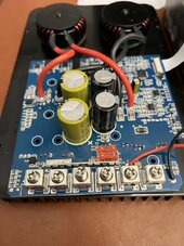
Two new caps on the right:
IMG_1375.jpeg

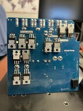
Cleaned up the mosfets on the bottom along with replacing one I suspect is shorted. Yes you can tell it's the shiny one on the left that's new.
IMG_1376.jpeg
 
Good job with the repair! I wonder why these things don’t have a crowbar circuit or at least a zener diode across the solar input to keep them from being fried if there’s a higher than expected voltage spike.
 
I would have replaced all of them and all 4 caps unless the parts were expensive enough to make the attempt not worth the trouble.

A number of the solder junction on the upper row of mosfets seem spotty, almost bridged. I would touch those up and inspect every other joint specifically for cracks a day bridges.
 
On the pv showing 3.2v I see that allot on my small controllers when the suns down or the pv isn't connected so I would bet that's normal for it.
 
On the pv showing 3.2v I see that allot on my small controllers when the suns down or the pv isn't connected so I would bet that's normal for it.
Whew good to know!

Yes, I checked all the solder joints to confirm I didn't bridge anything. I might have scraped off some conformal coating which is why it might look like there's solder.

Only if the mppt function is back working properly will it be worth replacing any additional components or caps. Not sure on the brand name of the caps but they look to be cheap ones. Digikey always comes through for items I've had to order, and they seem to carry good quality products.

There's also a idiotic stupid design where after the screw terminals is a large bar that you can bridge positive and negative against if you stick the leads in too far... It's like they want it to be destoryed...
 
Good job with the repair! I wonder why these things don’t have a crowbar circuit or at least a zener diode across the solar input to keep them from being fried if there’s a higher than expected voltage spike.
Because the Zener would have to be rated at 400W? And the crowbar would have to be rated at Isc for the maximum overpanelled case. Much easier to publish specs and require that they not be exceeded.
 

diy solar

diy solar
Back
Top