Hedges
I See Electromagnetic Fields!
- Joined
- Mar 28, 2020
- Messages
- 21,897
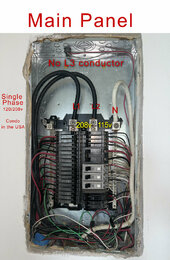
Perfectly normal for 3-phase with L1, L2, L3 all 115V relative to N, you get two legs L1, L2 and N.
120 x sqrt(3) = 208V, 115 x sqrt(3) = 199V.
That voltage between legs can vary a bit if loading changes its phase slightly.
They would only add up to 240V (or 230V because each is 115V not 120V) if 180 degrees apart. That would be split-phase.
The wattage you can pull at 202V will be less than the sum of inverter wattages, because current they can produce is the same (same heating of transistors and inductors) but voltage is out of phase. 202V / 240V = 84% of wattage available at 202V. But with separate 120V loads they could supply 100% of rating.
This drawing shows secondary windings of a transformer as if they were physically at 120 degree angles to each other, but is meant to represent AC waveforms at 120 degree phase shift from each other.
Note on the waveform that if you draw a vertical line and imagine putting a volt meter where the vertical line crosses two of the traces, it is never at the peak of both. (trace passes through Vpeak, but for A/C we quote RMS.)