diy solar

diy solar

EG4 18Kpv fried PV input

Jsands

New Member
Joined
Jul 12, 2023
Messages
32
Location
Olympia wa
Good day to you all,

I have an EG4 18kPV inverter. It has been up and running for about 2 months and as far as I could tell there were no issues. System was designed by and purchased from Signature Solar (which were great to work with by the way).

I had the system installed by a local Solar company.

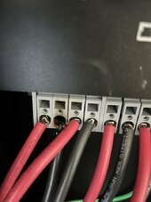
2 days ago, I noticed my solar production dropped by 25%. I opened the inverter door and the source of the problem was very apparent (see picture) - the 1st MTPP was fried.

the 10g PV wire was black/burnt too, going pretty far back on the wire itself.

MTPP #1A was the one that got cooked. #1B and #2 and #3 MTPP's were all working fine - hence the drop in 25% of my solar production.


my PV input array is as follows:

I have 36 Solorever 455W/49V panels. They are divided into four groups of 9 panels each (max wattage 4095 per grouping, 441V per grouping)

for the three MTPP inputs:
#1A (9 panels)
#1B (9 panels)
#2 (9 panels)
#3 (9 panels)

Has anyone ever seen this? Any ideas what could have caused this? Anyone every had to buy parts from SS/EG4 - as I will need to get new MTPP plug in ports.

I'm grateful for any input/suggestions/advice.
 

Attachments

  • IMG_9389.jpg
    IMG_9389.jpg
    88.1 KB · Views: 119
I have installed that inverter in the past. The instruction manual clearly states to use wire ferrules on the PV connections. The instructions were not followed as no wire ferrule are in use. Most likely there was a bent wire on insertion that resulted in arcing and a short. This is faulty installation and should not be a warranty coverage IMO, but a workmanship issue with your installer.
 
I have installed that inverter in the past. The instruction manual clearly states to use wire ferrules on the PV connections. The instructions were not followed as no wire ferrule are in use. Most likely there was a bent wire on insertion that resulted in arcing and a short. This is faulty installation and should not be a warranty coverage IMO, but a workmanship issue with your installer.
Thanks. They did use ferrules. But I do recall they really struggled to get them in.
 
Those are really lousy crimps on the ferrules.

I’ve just installed a pair of these, and you have to use a screwdriver in the top port to open the gate where the ferrule goes.

I’d recommend getting a different company to redo the ferrules and use an external combiner for at least the negative side of 1A, 1B.
 
This is not rocket science:

There can be upwards of 600Vdc on those terminals, don't do a half-fast job.

There should not be any wire exposed at those terminals. Regardless of the arcing potential, if you touch it, you can die.

Ferrules should be appropriately sized, insulated, fully crimped, and trimmed to length

When you press down on the mechanism inside the terminal, it opens the gate, then you press the ferrule all the way in, making sure it's fully inserted, and then release the gate to clamp down on the ferrule. Then tug on it to make sure it's correctly fastened.

Not that I'm any kind of an expert, but here's mine. Fully seated, sample ferrule, gate open, gate half-open.

IMG_7068.jpegIMG_7070 (1).jpegIMG_7071.jpegIMG_7072.jpeg
 
EG4 doesn't have replacement parts. The crimp on the ferrule looks poorly done. This failure is the result of a poor connection, most likely the poorly crimped ferrule, but could be on the other side of the connector.

I had a failure in the EG4 charge controllers. https://diysolarforum.com/threads/magic-smoke-came-out-it-happens.83412/ When I installed the replacement charge controller (remember, they don't have any parts to service units) I removed the top cover and tightened every terminal. Probably should do it again after running for a few months.

Are you paralleling strings? This should be about 10A for a single string.
 
I have installed that inverter in the past. The instruction manual clearly states to use wire ferrules on the PV connections. The instructions were not followed as no wire ferrule are in use. Most likely there was a bent wire on insertion that resulted in arcing and a short. This is faulty installation and should not be a warranty coverage IMO, but a workmanship issue with

Those are really lousy crimps on the ferrules.

I’ve just installed a pair of these, and you have to use a screwdriver in the top port to open the gate where the ferrule goes.

I’d recommend getting a different company to redo the ferrules and use an external combiner for at least the negative side of 1A, 1B.
What is an external combiner? I’m unfamiliar with this idea.
 
From what I remember reading there's no parts replacement program as such for the eg4 inverters, process is ship back to seller for unit replacement. But Jess may be able to help you out: @SignatureSolarJess
Hey! These are actually out of stock, we don't have an update on the ship date at this time 😕
 
Like Brucey's zoomed in picture shows:

Were they not tightened down enough? Or they screwed up the crimping of the ferrules on the pv wires?

View attachment 223489


Have to agree with wpns those are uninsulated ferrules and look to be way too big for the wire gauge aswell as being crimped with the wrong die.

The wire cross section is about 50% or less of the un-crimped ferrule opening.

Correct size, wire will just fit when opening is round, be tight when ferrule is crimped into a square, have all the air crushed out of it leaving a cross section of solid copper where the crimp tool dimples it.

1718977909001.png

Everything is a process, and if this was done with process controls, might include this:


Pull-test is the most basic check.


Some spring-loaded terminals may specify ferrules.
The ones in my SMA inverters, seems to be OK with just bare wire. But the factory connections inside the inverter were made with ferrules.
 
Hey! These are actually out of stock, we don't have an update on the ship date at this time 😕
Jess, is there another option? The fact they are out of stock is a good sign that at least a part can be ordered. Any other suggestions?

My install company is going to cover the cost as they too seem to think it was a bad install on those connectors.

thank you.
 
This is not rocket science:

There can be upwards of 600Vdc on those terminals, don't do a half-fast job.

There should not be any wire exposed at those terminals. Regardless of the arcing potential, if you touch it, you can die.

Ferrules should be appropriately sized, insulated, fully crimped, and trimmed to length

When you press down on the mechanism inside the terminal, it opens the gate, then you press the ferrule all the way in, making sure it's fully inserted, and then release the gate to clamp down on the ferrule. Then tug on it to make sure it's correctly fastened.

Not that I'm any kind of an expert, but here's mine. Fully seated, sample ferrule, gate open, gate half-open.

View attachment 223495View attachment 223496View attachment 223497View attachment 223498
you did a nice job and yoru pictures are really clear. thank you. I know when the installers were here they really struggled to get those windows open. Anyone found a trick to make the window open better/more?
 
Some spring-loaded terminals may specify ferrules.
The ones in my SMA inverters, seems to be OK with just bare wire. But the factory connections inside the inverter were made with ferrules.
I think all push in spring loaded terminals require a ferrule only clamp style like the wago 221/222 your allowed to use stranded.
 
you did a nice job and yoru pictures are really clear. thank you. I know when the installers were here they really struggled to get those windows open. Anyone found a trick to make the window open better/more?
There's a specific tool that looks like a bank of flat headed screwdrivers but that's generally just for removing, if you have the correct wire size and ferrule they should just push in.
 
Ferrule guide --


As @ThaiTaffy says you can just push them in, but with a super strong spring it can be much easier to use a jewlers screwdriver or allen T wrench of the right size to push the spring release when inserting.
 

diy solar

diy solar
Back
Top