diy solar

diy solar

EG4 18Kpv fried PV input

Good day to you all,

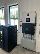
I have an EG4 18kPV inverter. It has been up and running for about 2 months and as far as I could tell there were no issues. System was designed by and purchased from Signature Solar (which were great to work with by the way).

I had the system installed by a local Solar company.

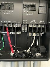
2 days ago, I noticed my solar production dropped by 25%. I opened the inverter door and the source of the problem was very apparent (see picture) - the 1st MTPP was fried.

the 10g PV wire was black/burnt too, going pretty far back on the wire itself.

MTPP #1A was the one that got cooked. #1B and #2 and #3 MTPP's were all working fine - hence the drop in 25% of my solar production.


my PV input array is as follows:

I have 36 Solorever 455W/49V panels. They are divided into four groups of 9 panels each (max wattage 4095 per grouping, 441V per grouping)

for the three MTPP inputs:
#1A (9 panels)
#1B (9 panels)
#2 (9 panels)
#3 (9 panels)

Has anyone ever seen this? Any ideas what could have caused this? Anyone every had to buy parts from SS/EG4 - as I will need to get new MTPP plug in ports.

I'm grateful for any input/suggestions/advice.
Yeah it looks like they did not insert it all the way. Bad installation as others have noted. You really need those ferrules to be inserted all the way in there unless this will happen every time.

They do not look like proper ferrules or crimped with a ferrule tool either. All bad.
 
I think all push in spring loaded terminals require a ferrule only clamp style like the wago 221/222 your allowed to use stranded.

Other spring-loaded terminals don't have external levers like those,

1718981492438.png


Rather they have a slot to insert a screwdriver, either push or pry to lift the contact.

SMA inverter manual:

"The conductors must be made of solid wire, stranded wire or fine stranded wire. When using fine stranded wire, bootlace ferrules must be used."

1718981591099.png
 
  • Like
Reactions: D71
Yeah it looks like they did not insert it all the way. Bad installation as others have noted. You really need those ferrules to be inserted all the way in there unless this will happen every time.

They do not look like proper ferrules or crimped with a ferrule tool either. All bad.
thanks Will. Sounds like my install company is going "own" it - now I just need to see if we can get a replacement MPPT terminal - any suggestions with that part of the solution?
 
Other spring-loaded terminals don't have external levers like those,

View attachment 223549


Rather they have a slot to insert a screwdriver, either push or pry to lift the contact.

SMA inverter manual:

"The conductors must be made of solid wire, stranded wire or fine stranded wire. When using fine stranded wire, bootlace ferrules must be used."

View attachment 223550
I know the style I'm quite surprised though, obviously manufacturers can suggest what they want but atleast in the UK it would be considered against BS7671 electrical regs I think they actually suggest ferrules for class 5 and 6 cables on all terminal types now for the exact reason above, to prevent strands or poor contact connections from creating arcs.
 
thanks Will. Sounds like my install company is going "own" it - now I just need to see if we can get a replacement MPPT terminal - any suggestions with that part of the solution?
It's a tricky one that best get in contact with SS I know Jess said they were out of stock but even if you could find a replacement part you would have to check how that would effect your warranty incase something else happened down the road
 
thanks Will. Sounds like my install company is going "own" it - now I just need to see if we can get a replacement MPPT terminal - any suggestions with that part of the solution?
If you absolutely need your system up and running, I would run another 48VDC MPPT.

Next I would get the exact part number from signature solar. @SignatureSolarJess do you know any other suppliers?

Could you post pictures of the rest of the connections on your 18kpv? Especially the battery terminals. Just want to ensure that the installer did not cause any other safety issues...
 
Could you post pictures of the rest of the connections on your 18kpv? Especially the battery terminals. Just want to ensure that the installer did not cause any other safety issues...
Completely agree with this damn take pictures of everything they touched and post, did they crimp any mc4 plugs?
 
If you absolutely need your system up and running, I would run another 48VDC MPPT.

Next I would get the exact part number from signature solar. @SignatureSolarJess do you know any other suppliers?

Could you post pictures of the rest of the connections on your 18kpv? Especially the battery terminals. Just want to ensure that the installer did not cause any other safety issues...
Thanks again for all the support.

Here are a few more pics. They came out yesterday and looked at it, cleaned it up and said they needed to get back to me on a solution.

Grateful for this group!
 

Attachments

  • IMG_9393.jpeg
    IMG_9393.jpeg
    114.8 KB · Views: 57
  • IMG_9394.jpeg
    IMG_9394.jpeg
    174.6 KB · Views: 58
  • IMG_9395.jpeg
    IMG_9395.jpeg
    153.3 KB · Views: 58
Thanks again for all the support.

Here are a few more pics. They came out yesterday and looked at it, cleaned it up and said they needed to get back to me on a solution.

Grateful for this group!
Pretty much everything has exposed conductors I know the terminals are obviously exposed but even so they don't seem to take all that much pride in their work.
Couple things that caught my eye especially with the current washer epidemic the neutral lug I marked in green is it making contact directly with the busbar no washers? And I can't see closely but do the battery cables I marked in red have steel ferrules on them inserted into the terminals?IMG_9394~2.jpeg
 
Pretty much everything has exposed conductors I know the terminals are obviously exposed but even so they don't seem to take all that much pride in their work.
Couple things that caught my eye especially with the current washer epidemic the neutral lug I marked in green is it making contact directly with the busbar no washers? And I can't see closely but do the battery cables I marked in red have steel ferrules on them inserted into the terminals?View attachment 223559
i think the battery wires are bare - no ferrules.

The white neutral wire you circled in green would have come stock from EG4 - but to answer your question I do see a tiny washer between the bolt and the wire connection terminal.
 
Thanks again for all the support.

Here are a few more pics. They came out yesterday and looked at it, cleaned it up and said they needed to get back to me on a solution.

Grateful for this group!
If you get a chance, I would shut down the entire system and put a torque wrench to those terminals to make sure they are at spec. You can also wiggle and pull the conductors to ensure they are at least mostly tight. Again, do not attempt until the system is completely shut down, batteries turned off, and grid input disconnected.
 
Pretty much everything has exposed conductors I know the terminals are obviously exposed but even so they don't seem to take all that much pride in their work.
Couple things that caught my eye especially with the current washer epidemic the neutral lug I marked in green is it making contact directly with the busbar no washers? And I can't see closely but do the battery cables I marked in red have steel ferrules on them inserted into the terminals?View attachment 223559
That much exposed conductor on the battery cables is fine, those cables are really tough to work with. As long as they are seated properly and torqued to spec it should be ok. Those plastic dividers between the terminals help a lot to separate the conductors.
 
While you're at it, I would make sure that L2 Grid wire is not leaning up against the Neutral screw. Can't tell from the picture if it is.
 
That much exposed conductor on the battery cables is fine, those cables are really tough to work with. As long as they are seated properly and torqued to spec it should be ok. Those plastic dividers between the terminals help a lot to separate the conductors.
Just a pet peve of mine is all even if it is safe I don't like to see bare conductors but I'm still confused why I can see a slither of conductor in the photo then it goes solid before entering the battery terminal.
 
I am going to ask a dumb question - but, aren't the CT clamps meant to go around the service entrance grid cables verse just the grid wires to the AIO? I mean they could just pick the presence and frequncy up internally from the terminals ?
 
I am going to ask a dumb question - but, aren't the CT clamps meant to go around the service entrance grid cables verse just the grid wires to the AIO? I mean they could just pick the presence and frequncy up internally from the terminals ?
Would make sense why there's such large spools of cables inside the unit.
 
I am going to ask a dumb question - but, aren't the CT clamps meant to go around the service entrance grid cables verse just the grid wires to the AIO? I mean they could just pick the presence and frequncy up internally from the terminals ?
Depends on what you are trying to do.
 
you did a nice job and yoru pictures are really clear. thank you. I know when the installers were here they really struggled to get those windows open. Anyone found a trick to make the window open better/more?
I literally spent hours looking this up. I'd never seen this style connector.

Place an appropriately sized screwdriver in the top I used a 10" bargain bin from Lowes.
1718989358362.png

Stuff it in the hole as far as you can flat high. Note the flat part is not visible.

1718989494806.png

Now peer in the hole and lift the handle , you will see the contact raise up inside the hole ... It takes quite a bit of pressure to move it!

1718989678225.png
Good luck!
 

diy solar

diy solar
Back
Top