Sometimes I wonder if posting ideas here is really such a good idea.
There was an epic thread by
@BiduleOhm, "DIY BMS design and reflection" it went for 36 pages and was excellent, and had a very strong following.
I have designed and built quite a few experimental BMS systems over the years myself, and now to my great regret posted some of the problems I encountered along the way, and how I overcame them.
I truly hoped others might profit from some of my own success in that direction.
That seems to have killed that thread stone dead.
Its now five months, and nobody has posted there since. Here is that last very lethal page.
https://diysolarforum.com/threads/diy-bms-design-and-reflection.4065/page-36
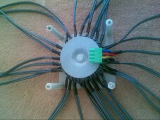
Another example, is that almost two years ago I came up with a way to build a really high power transformer cell balancer using a single large toroidal core with multiple low impedance windings.
For the technical, its a very low impedance forward converter, not flyback or using capacitors to transfer charge.
This produces extremely low impedance direct dc coupling cell to cell, and allows high balance current with very small millivolt cell to cell differences.
That was a quite unique approach at the time.
Going commercial with it would have been possible, but I knew if I did, the Chinese would copy the idea within a few months and sell them for less than the cost I can source components here in Australia to build them myself.
So for me, after a lot of work, there was more chance of losing money than making money.
I suggested this new approach over at the Back Shed Forum, and two people Mike, and Klaus built prototypes and obtained excellent results.
I knew it would be a total waste of time posting anything over here.
Anyhow, in recent times the Chinese are now making these and they are advertised on Ali Express, and the feedback from customers has been excellent.
Its so good, they even publish real genuine specifications I know are correct, which is unusual for the Chinese. Eight amps of balance current for a cell differential of 100mV, diminishing to zero current at 0mV differential.
That suggest a total cell to cell coupling impedance of about 12.5 milliohms which is quite realistic.
I was doing only slightly better than that myself two years ago, and it craps over any of the capacitor balancers everyone seems to be using.
So Great business for the Chinese, and great for us too as users. This is the new big thing in future commercial cell balancers I am sure.
If you do an internet search on transformer balancers, there is a fair bit of discussion, and all it quite recent.
But as far as I know, I was the first to come up with the idea.
But as a Forum DIY project it would be a complete total waste of my time to go to the trouble of explaining how it actually works, or show people how to put one together themselves.
The Chinese figured it all out very quickly.
They are smart, and work very hard, which is why we in the West are DOOMED.
https://www.aliexpress.com/item/100...nCirhZzm&utparam-url=scene:search|query_from:
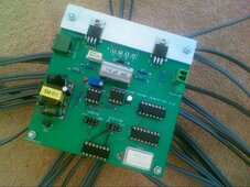
Here are some now quite old pictures I took of my original first prototype.


 If I can power it up I'll probe it with an oscilloscope /logic analyser until I find some clue what's wrong or I get tired and it lands in "things to fix in future" box.

")
