• Have you tried out dark mode?! Scroll to the bottom of any page to find a sun or moon icon to turn dark mode on or off!

diy solar

diy solar

Repairing inverters...

I notice several of the contributors to this thread are new members. I agree with all the sentiment expressed but I have found a distinct lack of interest in electronics on this site.

I recently repaired a Fronius GTI but there was no reaction to the thread at all so I simply stopped posting.
Please keep posting. There's often no rhyme or reason to why some posts get ignored.
 
I notice several of the contributors to this thread are new members. I agree with all the sentiment expressed but I have found a distinct lack of interest in electronics on this site.

I recently repaired a Fronius GTI but there was no reaction to the thread at all so I simply stopped posting.
Don't feel too bad. Our knowledge of electronics exceeds the capabilities of approximately 99% of the people that come here. Most visitors are just after information about solar and how to make it work. I also used to post technical information and came to the same conclusion as you. It's not worth the time since nobody really cares.
 
I notice several of the contributors to this thread are new members. I agree with all the sentiment expressed but I have found a distinct lack of interest in electronics on this site.

I recently repaired a Fronius GTI but there was no reaction to the thread at all so I simply stopped posting.
I must have missed your thread. I'm very interested in board level repair, but I'm also fairly new to the site.

I agree there is what could be called lack of interest. And on more repair focused forums like eevblog there is a lack of interest in solar stuff...

I find it strange, power electronics is one of the most satysfying things to repair and relatively simple compared with mobile phones etc. Also there is a lot less tools required. I consider a good desoldering station a must for desoldering mosfets etc. But it does contain lethal voltages and that is quite intimidating.

I do board level repair on surface mount (including BGA reflow) and through hole stuff. I'd love there to be more resources out there. Maybe even an open driver for some common inverter board.

The most difficult part of today's electronics is firmware and the sheer number of various MCUs. Between grinding off the markings and Knoxkoffs made in China... Unless there is a serial console header on board you can access easily it is a real pain.

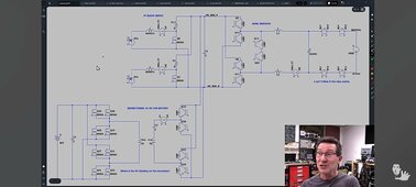
Coming back to inverters. I recently saw very good YouTube video from the eevblog Dave. In there he had a drawing made by a forum member that showed a diagram of a deye hybrid inverter being dismantled. I think anyone repairing these things will find it useful. Screenshot_1718202296780.jpg
 
Sometimes I wonder if posting ideas here is really such a good idea.

There was an epic thread by @BiduleOhm, "DIY BMS design and reflection" it went for 36 pages and was excellent, and had a very strong following.

I have designed and built quite a few experimental BMS systems over the years myself, and now to my great regret posted some of the problems I encountered along the way, and how I overcame them.
I truly hoped others might profit from some of my own success in that direction.

That seems to have killed that thread stone dead.
Its now five months, and nobody has posted there since. Here is that last very lethal page.
https://diysolarforum.com/threads/diy-bms-design-and-reflection.4065/page-36

Another example, is that almost two years ago I came up with a way to build a really high power transformer cell balancer using a single large toroidal core with multiple low impedance windings.
For the technical, its a very low impedance forward converter, not flyback or using capacitors to transfer charge.

This produces extremely low impedance direct dc coupling cell to cell, and allows high balance current with very small millivolt cell to cell differences.
That was a quite unique approach at the time.

Going commercial with it would have been possible, but I knew if I did, the Chinese would copy the idea within a few months and sell them for less than the cost I can source components here in Australia to build them myself.
So for me, after a lot of work, there was more chance of losing money than making money.

I suggested this new approach over at the Back Shed Forum, and two people Mike, and Klaus built prototypes and obtained excellent results.
I knew it would be a total waste of time posting anything over here.

Anyhow, in recent times the Chinese are now making these and they are advertised on Ali Express, and the feedback from customers has been excellent.
Its so good, they even publish real genuine specifications I know are correct, which is unusual for the Chinese. Eight amps of balance current for a cell differential of 100mV, diminishing to zero current at 0mV differential.
That suggest a total cell to cell coupling impedance of about 12.5 milliohms which is quite realistic.

I was doing only slightly better than that myself two years ago, and it craps over any of the capacitor balancers everyone seems to be using.

So Great business for the Chinese, and great for us too as users. This is the new big thing in future commercial cell balancers I am sure.
If you do an internet search on transformer balancers, there is a fair bit of discussion, and all it quite recent.
But as far as I know, I was the first to come up with the idea.

But as a Forum DIY project it would be a complete total waste of my time to go to the trouble of explaining how it actually works, or show people how to put one together themselves.
The Chinese figured it all out very quickly.
They are smart, and work very hard, which is why we in the West are DOOMED.
https://www.aliexpress.com/item/100...nCirhZzm&utparam-url=scene:search|query_from:

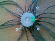
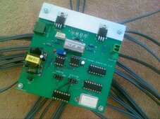
Here are some now quite old pictures I took of my original first prototype.
 

Attachments

  • 2022-10-29_0001.jpg
    2022-10-29_0001.jpg
    300 KB · Views: 14
  • 2022-09-01_0002.jpg
    2022-09-01_0002.jpg
    299.9 KB · Views: 14
Sometimes I wonder if posting ideas here is really such a good idea.

There was an epic thread by @BiduleOhm, "DIY BMS design and reflection" it went for 36 pages and was excellent, and had a very strong following.

I have designed and built quite a few experimental BMS systems over the years myself, and now to my great regret posted some of the problems I encountered along the way, and how I overcame them.
I truly hoped others might profit from some of my own success in that direction.

That seems to have killed that thread stone dead.
Its now five months, and nobody has posted there since. Here is that last very lethal page.
https://diysolarforum.com/threads/diy-bms-design-and-reflection.4065/page-36
I have observed this "thread killing" by really valuable and technical posts on many forums including by myself. I'm not entirely sure why this happens, but I suspect it has something to do with the fact many people are interested in reading such threads (and they are an amazing resource if you find them years later by Google when they mention a solution to a problem you have), but I suspect many readers don't feel they can contribute at the same level so the thread dies. Especially on highly active forums most people consume through the "new posts".

Still I'd encourage you to post ideas and other technical stuff anyway as it is very valuable despite the lack of engagement.


Another example, is that almost two years ago I came up with a way to build a really high power transformer cell balancer using a single large toroidal core with multiple low impedance windings.
For the technical, its a very low impedance forward converter, not flyback or using capacitors to transfer charge.

This produces extremely low impedance direct dc coupling cell to cell, and allows high balance current with very small millivolt cell to cell differences.
That was a quite unique approach at the time.
I never heard of it and now I did. Thank you. It is a great idea I'd definitely buy, but I have to admit I do prefer the prices of Chinese knockoffs. I'd say from the point of view of sharing your idea with the world it has been very successful, but it feels bitter when others seem to be making money off your idea.

But as a Forum DIY project it would be a complete total waste of my time to go to the trouble of explaining how it actually works, or show people how to put one together themselves.
The Chinese figured it all out very quickly.
They are smart, and work very hard, which is why we in the West are DOOMED.
https://www.aliexpress.com/item/1005006073402783.html?spm=a2g0o.productlist.main.35.54a24b2dtyotda&algo_pvid=6b996848-c6a1-4d91-aee2-199c6659e504&algo_exp_id=6b996848-c6a1-4d91-aee2-199c6659e504-17&pdp_npi=4@dis!AUD!71.97!63.24!!!343.55!301.89!@2103241117188377948538471e492b!12000035607952743!sea!AU!0!AB&curPageLogUid=Wmo3nCirhZzm&utparam-url=scene:search|query_from:

Here are some now quite old pictures I took of my original first prototype.
You know if I had something like this I wanted to share I'd probably post it. I'd explain the tech stuff at a pretty high level. If people tried replicating it and had same problems I did I'd help them. But in such thread if I had posters asking for low level explanations of physical principles or with fundamental misunderstandings I'd probably just mention them and leave the task of clarifying to others.
 
Those transformer Chinese balancers don't work as well as the advertisers would have you believe, I have made my own balancer based on Warpspeeds original design, and they can work very well. I did purchase one off Aliexpress, an 8 series cell just to see what was in it. Seems they use a push pull inverter on each cell, all synchronized together, this differs from Warps forward converter on each cell.

When each cells inverter runs, by simple transformer action, any cell with a higher voltage will add extra charge current to a lesser voltage cell, this happens on each 1/2 switching cycle, so almost 100% of the time. However the huge currents they say you will get on these Chinese devices only occur if the cell voltages differ by almost 1 volt, not at 0.1v as advertised. Their transformer windings have pretty thin wire and the pcb tracks are not very large, so their impedance is higher than what can be achieved in a robust DIY design.

Cheers
Mike
 
Hi Mike.
Klaus was pretty happy with the version he built as well, he copied my design pretty much exactly.
The wire and tracks on those Chinese versions do look a bit thin, but I would have thought it should still work reasonably well.
But as we both know, the secret to success is keeping all the resistances of the cell wiring absolutely minimal.
I still think this concept still has rather a lot going for it.
 
I have repaired a few of those Chinese inverters, mainly its obvious what has blown up, causes seem primarily because of cheap under-spec components like capacitors, once these let go, then its cascade failure of any mosfets etc being powered by them. Its really guess work if you can fix them as schematic's etc are not to be found.
As the eeblog says, they will say they have named brand components, but quite often not.

Cheers
Mike
 
You can be lucky sometimes.....

I was once asked to fix a Make Sky Blue solar controller by a Forum member. I discovered that the problem was a really small transformer that supplied some isolated dc power to the isolated input section of the controller.
As I remember, it had an open circuit winding, the whole transformer was about a 10mm cube in size, using hair fine wire, and all epoxied together into a solid lump.
Impossible to dissect and reverse engineer as is often possible with larger transformers.
So not really fixable, at least not realistically with all the time and effort that would be involved in designing a replacement from scratch.

As a replacement solar controller would not be all that expensive, that was the final outcome.

Its interesting though. Many non technical people seem to think that because something only cost a couple of hundred dollars to buy new, it should also be fixable very cheaply. It difficult to explain to them that it might take at least a full days work plus the cost of the parts.
Also, if you do fix it, and it blows up again in a years time, the second blow up is all your fault.
 
Last edited:
Many non technical people seem to think that because something only cost a couple of hundred dollars to buy new, it should also be fixable very cheaply. It difficult to explain to them that it might take at least a full days work plus the cost of the parts.
You should try explaining to the 3rd owner of a $100k BMW or Benz why their repair estimate costs more than they purchased the 12 year old 200,000 mile car for...
"What do you mean it's $8,000 to fix this one problem and $12,000 to fix most of the worst stuff wrong with it?"
Also, if you do fix it, and it blows up again in a years time, the second blow up is all your fault.
I feel that pain.

I've got a question for you guys that do PCB level repair. How do you get started? I can typically find a cold/cracked solder or bulged capacitor, but past that I've never had luck. I can start probing voltages and following the inputs or measuring for shorts (whichever is applicable) but I've never had much luck making heads or tails of a PCB. My brain just needs a wiring diagram.
 
I've got a question for you guys that do PCB level repair. How do you get started? I can typically find a cold/cracked solder or bulged capacitor, but past that I've never had luck. I can start probing voltages and following the inputs or measuring for shorts (whichever is applicable) but I've never had much luck making heads or tails of a PCB. My brain just needs a wiring diagram.
In my case reverse engineering mixed with a heavy dose of intuition. Having spent a lifetime designing circuits there are only so many way's something can be arranged so the schematic forms itself in my head lols Most of all collecting clues and a process of elimination, especially useful are error codes and interpreting chinglish writings!
 
I notice several of the contributors to this thread are new members. I agree with all the sentiment expressed but I have found a distinct lack of interest in electronics on this site.

I recently repaired a Fronius GTI but there was no reaction to the thread at all so I simply stopped posting.

It is a normal reaction, most of guys are very good in knowing the business very well, but that not means that they are experts in electronics. Those post will become handy on a day when one of us will encounter a failure, so then you will get your reward. In my case I posted a thread with modification of easun 6048 charging controller, and it took several weeks before someone get interested and followed my project.

So posting our "advanced" stuff is mostly for guys with "this thing" that allows them to overcome the "magic smoke" work, especially when it is needed.
In fact we need to admit that working on inverter is a dangerous work, as one could get electrocuted or melt all home appliances in no time...
 
I experienced the golden age of electronics where a circuit was almost visual in the way it laid out. Now packaging makes it almost impossible to repair anything. At least I lose interest before I even start. A while back on another forum fourtytwo did a PV boost water heater build. He has never posted it here. This is a very non technical forum and the majority do not understand the fundamentals of solar panels, ohms law or basic math (like the power of squares). There is nothing that teaches you more about principals of solar than heating water. And almost nobody here can heat water effectively. At first I thought it was amazing that a whole industry was built upon a community that had no understanding of what they were doing. But then that is the automotive industry. If you can open the door and find the key, you are good to go. Hook four wires up to a charge controller and your mother can tell anybody who will listen that their child is an electrical genius. And most people just want to accomplish a task, not know why it works. Electronics takes some investment of time and money.
 
You can be lucky sometimes.....

I was once asked to fix a Make Sky Blue solar controller by a Forum member. I discovered that the problem was a really small transformer that supplied some isolated dc power to the isolated input section of the controller.
As I remember, it had an open circuit winding, the whole transformer was about a 10mm cube in size, using hair fine wire, and all epoxied together into a solid lump.
Impossible to dissect and reverse engineer as is often possible with larger transformers.
So not really fixable, at least not realistically with all the time and effort that would be involved in designing a replacement from scratch.
That is really a bummer when it happens. You know what's broken, but you can't find a replacement part.

I've recently found a good cache of Voltronic service manuals.(if there is interest I'll post) Although they are written for other devices than what I have I can see the same functional blocks being reused. This will ve immensely helpful when they break.
I've got a question for you guys that do PCB level repair. How do you get started? I can typically find a cold/cracked solder or bulged capacitor, but past that I've never had luck. I can start probing voltages and following the inputs or measuring for shorts (whichever is applicable) but I've never had much luck making heads or tails of a PCB. My brain just needs a wiring diagram.
For me it is often one or the other:
- if I have a service manual, the markings have not been ground off chips, I have schematics or the circuit is laid out easily and I know how it works it is pretty straightforward.
- option two, far more common, I have no clue whatsoever, it uses a 6 layer board and marking off chips have been ground off, are

In such case I just do the basics, is anything burned? If there are mosfets/diodes are they busted? If I can power the circuit does any part get hot? (a thermal camera is an amazing tool). If all fails and I can't power it up it goes into a junk drawer 😕 If I can power it up I'll probe it with an oscilloscope /logic analyser until I find some clue what's wrong or I get tired and it lands in "things to fix in future" box.

Also If it has markings on chips I find what they are(this becomes increasingly difficult with some companies putting 1-3 letters on tiny smd chips - good luck researching it), their datasheets and application circuits.

Also I have a soldering microscope for smd and tiny "mobile phone pcb repair" insulated wire with solder through insulation. It makes it possible to hook up to the tiniest of chips.
Also, if you do fix it, and it blows up again in a years time, the second blow up is all your fault.
This is why I don't fix stuff for others (except close family). For myself when a thing breaks it almost always happens on a Friday afternoon (Murphy's law etc) so fixing it is the only way to have the device not be off till mid next week. I tend to buy replacements then anyway to have as a spare. Then of course the original never breaks again 😁
So posting our "advanced" stuff is mostly for guys with "this thing" that allows them to overcome the "magic smoke" work, especially when it is needed.
In fact we need to admit that working on inverter is a dangerous work, as one could get electrocuted or melt all home appliances in no time...
I'm not even bitter there is not that much interest here, but I am that on electronics focused forum there is also. Post some high power high voltage related stuff and people assume you're a beginner and there are 3 pages of how you're going to electrocute yourself, how shit Chinese electronics is and this design in particular, how you're a fool for not mortgaging your house and buying western made stuff and so on... Everything, but the answers to actual questions you ask when troubleshooting... This is pretty disappointing.

I experienced the golden age of electronics where a circuit was almost visual in the way it laid out.
I collect lots of vintage electronics and I have quite a few vacuum tube devices including this HP a voltmeter made in 1960s:
Compress_20240622_130634_4547.jpg
It is extremely sensitive and the problem is it starts self resonating few minutes after it's powered on.

I have the service manual and a schematic(of a very similar model). I've been at it twice and I still haven't fixed it.

Give me any modern device I have so much info on and I've probably fixed it long ago. So let's not overestimate the good old days :-)

Unless you mean a specific time for example 1970s. Yes I love high end (usually ham radio and test) equipment made in 1970s. It is all semiconductor based except high power and RF amplifiers so it is fairly easy for me. Often service manuals co tain not just schematics, but a good discussion how the circuit works and troubleshooting steps as well as images of both sides of the PCBs and the soldermask so you can remake a pcb if required... That was absolutely amazing and we should go back to documentation like this.
Now packaging makes it almost impossible to repair anything.
I do enjoy working with tiny tweezers under a microscope :-) I actually like SMD stuff since I bought the microscope.

Hook four wires up to a charge controller and your mother can tell anybody who will listen that their child is an electrical genius. And most people just want to accomplish a task, not know why it works. Electronics takes some investment of time and money.
This👍
 
I've got a question for you guys that do PCB level repair. How do you get started?
I start with the error messages and then google it for previous repairs, other than using a multi-meter that also measures capacitance the other tool I use is a microscope for viewing the board tracks, soldering and the writing on the smd component's. I am more used to rebuilding engines so not a natural environment for me but the money saving is good.
 
I can't live without a digital microscope to see the printing on SMD. I also can no longer read resistor values. When I was young, I had a tray of hundreds of resistors and not only could find the resistor I needed quickly, but could find one of close enough value to use. It is not that my sight is gone, the colors are so muted you can't tell the difference between red, brown and violet. I have to use a meter. It shocks me to find what the value is compared to what I thought I saw.

It is not that equipment was better in the old days, just designs were more obvious. I started out with my first electronics book in the third grade. Teacher told my mother it was inappropriate for me. My first job was repairing transistorized electronic organs when I was 14, my brother had to drive me on service calls. It was the early 60's and nobody knew about transistors. You were golden if you knew electronics back then. Taught me a lot about people. Those with a used $200 organ would stand around asking if I knew what I was doing. Someone with a $5,000 organ would bring me milk and cookies. Spent a lot of time in bars and backstage with bands at 15. And then there was the golden age of audio. Fixing high end stuff put me thru college. I knew Saul Marantz. He was a funny guy who told some great stories. By training he was a graphic artist. Back then a lot of great stuff came from experimenters. Now everything is just on a chip or you buy a module.

I used to buy dead inverters and other electronics in ebay dirt cheap. It was nothing but e-waste. Now with YT videos everybody must think they can repair them and they go for prices I would never consider. One thing to remember in repair is form follows function.

.
 
Sometimes I wonder if posting ideas here is really such a good idea.

There was an epic thread by @BiduleOhm, "DIY BMS design and reflection" it went for 36 pages and was excellent, and had a very strong following.

I have designed and built quite a few experimental BMS systems over the years myself, and now to my great regret posted some of the problems I encountered along the way, and how I overcame them.
I truly hoped others might profit from some of my own success in that direction.

That seems to have killed that thread stone dead.
Its now five months, and nobody has posted there since. Here is that last very lethal page.
https://diysolarforum.com/threads/diy-bms-design-and-reflection.4065/page-36

I'm still here, and still plan on completing this project, it's just on pause for now. Long story short, life is complicated and more urgent/important things got in the way.
 

diy solar

diy solar
Back
Top