diy solar

diy solar

Repairing inverters...

Externet

New Member
Joined
May 26, 2021
Messages
99
Location
Mideast U.S.A.
Hi.
Perhaps the wrong forum section for the subject; but can be dangerous for many without proper procedures and servicing instructions.
Do service manuals exist or are they plainly unobtanium for the many brands / models on the market ?
At least; if no schematics are available to the public; do helpful block diagrams of inverters exist ? Nothing wrong with protecting copyright circuitry and patents; but do 'authorized' service centers have access to repair information, upgrades, proper parts ?

Do you know of any published repair /service / upgrade / troubleshooting / schematics somewhere; current or obsolete ?

Is it safe to assume H6 (as in Delta/Tesla inverters) is a topology and not just a lettersoup model from manufacturer ?
----> http://www.ijatir.org/uploads/143526IJATIR5952-210.pdf

-Please move if deserved-
 
I am afraid full service manuals or factory spare parts for anything these days are just not available.
Many reasons for that.

The first is that if you spend a lot of money developing a new product over say two years of R&D, and then try to sell it, you will find that within a few weeks, some Chinese company are advertising an identical clone at a price you cannot compete with, and you go out of business.
The Chinese even do it to each other.
So what you do is try to make your new product as difficult to copy as possible, by deliberately trying to hide how it works.

Writing a detailed service manual in twelve different languages with all the pictures and drawings requires highly competant technical people, and its expensive to produce and print. As your product may only have a commercial lifetime of a few months, before the next model is produced, its just not cost effective, as the product has PLANNED OBSOLESCENCE anyway.

For the same reasons, no spare parts are warehoused for previous obsolete models. Its also not cost effective for even the manufacturer to repair warranty returns these days. If it fails in service, within the warranty period, get some minimum wage slave to check fuses, and that the battery is o/k, and if its not some obvious problem, just trash it, and give the customer a brand new unit.
I have worked for a company that did exactly that.

Why pay someone $20/hour to spend an afternoon fixing something only worth $40 ($200 retail to the customer).

And on it goes. Its cheaper to just churn out the stuff in China and the eventual customer be damned.
Its the highest form of consumer capitalism.
Only money matters.
 
Last edited:
Why pay someone $20/hour to spend an afternoon fixing something ....... I got more than that 40 years ago!

If you have to ask how to fix something, you probably can't even if there was a manual available.
 
Some people are lucky to earn that much even today, believe it or not, even in first world countries.

Back in ancient times components were large enough to have values or at least a colour code printed on them, and component designators printed on the circuit board. Circuit boards only had one or at most two layers, and tracks could be easily followed, and with patience the entire circuit traced out.
No secret software or proprietary chips either back then. Even without any service information, equipment was often simple enough to follow right through and figure out what it all does.

Not so these days.
With multilayer boards with internal hidden layers, surface mount components without identification, and no component designators on the board, its pretty much impossible to trace out a circuit. Then there are programmable chips that cannot be read or identified, and absolutely no way to get a replacement if the company is uncooperative or no longer in business.

Just about anything electronic these days is disposable, and just not repairable. And its made that way deliberately.
 
Its a bloody shame that component level repair has essentially been eliminated due to greed and 'planned obsolescence'.

Plus, as mentioned, current manufacturing methods make repair extremely difficult, even with provided info.

The only real solution to the problem is to DIY at the component level, using discrete parts, Arduino and PI to handle the digital logic elements. Some components on the Arduino and Pi boards (like USB controllers) are readily replaceable.

What is nice is that old TTL chips have holders, and that at the current amperage levels for solar and many other types, that some fairly ancient high current devices can work just fine.

In the old days a DAC was an expensive chip, whereas today a better DAC in a cheap NANO is a fraction of the price.

Combining old Analog with modern modular digital allows alot of room for design variation plus a reasonable repairability if something goes poof.
 
Its a bloody shame that component level repair has essentially been eliminated due to greed and 'planned obsolescence'.

Plus, as mentioned, current manufacturing methods make repair extremely difficult, even with provided into.

The only real solution to the problem is to DIY at the component level, using discrete parts, Arduino and PI to handle the digital logic elements. Some components on the Arduino and Pi boards (like USB controllers) are readily replaceable.

What is nice is that old TTL chips have holders, and that at the current amperage levels for solar and many other types, that some fairly ancient high current devices can work just fine.

In the old days a DAC was an expensive chip, whereas today a better DAC in a cheap NANO is a fraction of the price.

Combining old Analog with modern modular digital allows alot of room for design variation plus a reasonable repairability if something goes poof.
 
Thanks to ALL for the opinions.
I can repair anything electronics if I learn how it works. It has been my spoon 45 years. A manual teaches how it works, test procedures and diagnostics.
When parts are available, much easier. If parts are unobtanium, the resource is replacing modules/boards... As long as vision, steady hands, test equipment and functioning brain are there. :(
 
A few years ago when I finally decided to go off grid, the first thing I did was a complete energy audit of every electrical product in the house.
That led to tossing out a lot of my old kilowatt hour munching dinosaur appliances.

So I bought an almost new current model low energy refrigerator off e-bay for less than half the new sticker price.
I soon found out why it was so cheap.... It would intermittently stop working, destroying a lot of food.

After a bit of frustrating fault finding I determined all the sensors and switches were o/k and the problem was on the main microcontroller board.

No problem, buy a new circuit board, except I was told it would cost almost as much as a whole new refrigerator !
I spent hours looking at that board for cracks, dry joints and heat sensitive components, and eventually gave up on it.

Clearly the manufacturer would rather sell me a new refrigerator rather than help me to fix this one. BASTARDS !!

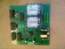
However, the user manual gave a detailed description of how it all worked, how the automatic defrost cycle works, and how that is modified by the number of door openings, and total accumulated motor run time and so on. So I thought I can do that with a very few digital counters, some logic gates and voltage comparators. No need for a microcontroller. So I built my own damned circuit board plus a spare. Plugged in the sensors and its still working perfectly today.

I am now in the happy situation of knowing exactly how it works, have a spare circuit board and can almost certainly fix anything likely to go wrong with it in the future.
This is my spare circuit board:
 

Attachments

  • 2022-06-17_0001.jpg
    2022-06-17_0001.jpg
    1,010 KB · Views: 40
I've long since given up trying to repair consumer level kit. I fell at the first hurdle looking at an LED TV that was emitting smoke whilst still actually functioning, I couldn't even get the back off. I bought a new one and gave the iffy one to my step-son who had it sorted by a local TV-chap for some nominal fee, it's in the grandkids bedroom now.

Meanwhile I'm not averse to looking inside faulty solar kit, the power devices are the usual failure point and they are still big enough for me to see. Many even have markings so replacements can be obtained.

I've also had luck talking to the technical support chaps of a couple of Chinese manufacturers. They won't give you diagrams or manuals for reasons discussed earlier, but they may well help out with defining the "stock faults" which happen commonly. "Replace Q10 and Q20, D1 is usually blown too" kind of thing, it really never hurts to ask.

Power electronics often suffers from "domino effect" where one device failing takes out several others, if you don't replace them all it all goes "pop" again. Long ago I used to buy "PSU repair kits" for satellite receivers (notably Pace 9000 series - it really was that long ago), replace all the bits in the bag and it would work again, no diagnostic skills needed.

I still do a bit of electronic design as a hobby and I'm not averse to throwing in an Arduino or ESP8266, but I'm not going to design an inverter or even an MPPT, too much risk of conflagration and they're not really that expensive to buy if you factor in your time.
 
Last edited:
So I thought I can do that with a very few digital counters, some logic gates and voltage comparators. No need for a microcontroller. So I built my own damned circuit board plus a spare. Plugged in the sensors and its still working perfectly today.
?????

Yeah, I do not need a microcontrolled-triple-expensive clothes dryer to call me on the phone to tell me it is done drying.
 
A guy I found on YouTube once repaired relays on solar inverter, they were not clicking on for some reason so he opened the relays up and bent the connections until they came on easily. He then set it up with fake loads as if it was in a working solar array/system and he showed that they would now actually work, the reason I found the video was he was messing with the same make of inverter (zeversolar previously eversolar) that we had and our relays had just stopped working.

Fortunately, cos we knew the person who installed our system and it was within a 3 year warranty they just replaced it free of charge.
 
Sometimes you can be lucky...

But sadly, when an inverter fails, its often pretty violently, and all you are left with is smoke stained devastation to work with.
 
An apparent nearby lightning strike took out our 15 year old Outback 24V 3500W inverter. The fellow who put it in has been retired but was in our neck of the woods so came by and called Outback tech help. He had an old installer number with Outback and we talked. After trying several checks (there were absolutely no fault codes) that I had done numerous times Outback said to replace the control board first, then the FET board. Control board was less than $400 I think and FET board was seemingly out of stock but looked like it was maybe $800 when available? We chose to buy an updated model that dropped right on the Midnite Solar back panel. I disassembled that broken inverter and never saw a burnt part or anything untoward. Nor was I able to bypass the electronics to get basic function.
 
I have an Ampinvt 6000W split phase inverter.

For a few weeks of daily use it worked fine. Now, it works fine, but the DC amps are oscillating. If I have a load that should draw around 70A DC, the DC current is swinging from 0 to 150A. I put a digital ammeter shunt inline on the DC side and took 2000 samples at 4.678ms per sample and plopped that into a discrete Fourier thingy and have proven to myself that this thing is oscillating at 60hz.

I assume that there are a capacitor(s) (or maybe inductors) that are supposed to smooth this out, so that the battery does not have to deliver 2x current and deliver it at 60hz.

Am I right? Is my inverter broken? Ampinvt support is telling me this is normal, but I find this hard to believe.

I am now in the happy situation of knowing exactly how it works, have a spare circuit board and can almost certainly fix anything likely to go wrong with it in the future.
I would very much like to be in this situation. Can someone tell me what to look for and potentially fix?

I am reasonably handy with circuits having designed my own BMS (the cells send their volts and temps via bluetooth no less). However, for the most part that is all digital. I'm saying I can buy, remove, and solder in parts, if I knew what to look for.

Any advice is greatly appreciated.
 
I have an Ampinvt 6000W split phase inverter.

For a few weeks of daily use it worked fine. Now, it works fine, but the DC amps are oscillating. If I have a load that should draw around 70A DC, the DC current is swinging from 0 to 150A. I put a digital ammeter shunt inline on the DC side and took 2000 samples at 4.678ms per sample and plopped that into a discrete Fourier thingy and have proven to myself that this thing is oscillating at 60hz.

I assume that there are a capacitor(s) (or maybe inductors) that are supposed to smooth this out, so that the battery does not have to deliver 2x current and deliver it at 60hz.

Am I right? Is my inverter broken? Ampinvt support is telling me this is normal, but I find this hard to believe.


I would very much like to be in this situation. Can someone tell me what to look for and potentially fix?

I am reasonably handy with circuits having designed my own BMS (the cells send their volts and temps via bluetooth no less). However, for the most part that is all digital. I'm saying I can buy, remove, and solder in parts, if I knew what to look for.

Any advice is greatly appreciated.

I don't know your inverter, is it a low-frequency beast or a high-frequency "transformerless" design? Without knowing what the current was doing before you noticed the readings jumping around it's difficult to tell if it's normal.

I'd pop the lid off and look for any "burst" or bloated capacitors.
 
I don't know your inverter, is it a low-frequency beast or a high-frequency "transformerless" design? Without knowing what the current was doing before you noticed the readings jumping around it's difficult to tell if it's normal.
It is a low frequency beast. It has a nice big round transformer. It is a heavy unit.
I'd pop the lid off and look for any "burst" or bloated capacitors.
I am going to do that but am hoping to get some "architecture" description help. I mean something that describes what I'll find at the input side and output side and what, if any, these input capacitors will be like.
 
Back
Top