diy solar

diy solar

DIY BMS design and reflection

Hum... those cute little things are very tempting: https://www.mouser.fr/ProductDetail/Kingbright/ACPSC04-41SURKWA?qs=f499HRGa1Rk4yoQFJddBTg==

I'm thinking of 4 digits for the value + 2 alphanumeric ones for the units or cell number. The display would be something like 3.123 12 to say cell #12 is at 3.123 V, for capacity it would be 123.4 AH, for current it would be 123.4 A, ... for example.

What do you think? worth the 15 $? or just have the LEDs annunciators and use the ethernet interface for everything else? it's just that I think a simple physical display can be useful in addition to the ethernet.
Wouldn’t an OLED or 4x20 serial LCD be. More cost effective and versatile display solution?
 
I like the clarity of discrete annunciators; you know all the states at a glance, and having a screen means a lot more data to send (and as the MCU already has a lot of things to do, the less data I have to send the better). Also screens have a far lower contrast. And they require a lot more than the 3 wires I have (unless you put another MCU near the screen but that gets a bit too much then...).

I just thought I can always plan with the 7 segments display but don't populate it if you don't want it, no?
 
Touch screen? Some have a sd card slot for data logging. Can then display logged data on screen.
 
That's on the opposite end of what I want for the HMIB. But you can have a touch screen driven by an arduino or raspberry pi or whatever connected on ethernet port if you want to.
 
And they require a lot more than the 3 wires I have (unless you put another MCU near the screen but that gets a bit too much then...).
Serial LCDs only require clock and data lines, one less than shift registers to drive LEDs. With appropriate pin selections (A4,5), both options could be made available in the design.
 
I checked and you're right ;) but still doesn't change the other things.

Also, I wonder about a beeper: is it needed? or just annoying?
 
I checked and you're right ;) but still doesn't change the other things.

Also, I wonder about a beeper: is it needed? or just annoying?
I’ve disconnected the beeper on my Chargery BMS, and instead rely on the red LED to get my attention, so I’m not a fan of beepers. Others may think otherwise, so maybe it’s a good option?
 
I like the clarity of discrete annunciators; you know all the states at a glance, and having a screen means a lot more data to send (and as the MCU already has a lot of things to do, the less data I have to send the better). Also screens have a far lower contrast. And they require a lot more than the 3 wires I have (unless you put another MCU near the screen but that gets a bit too much then...).

I just thought I can always plan with the 7 segments display but don't populate it if you don't want it, no?

I agree with your primary premise that dedicated indicators can convey critical data in concise, non-dependent ways that are likely more focused than an LCD, OLED, or screen... What I'm questioning however is the mCU overhead trade off?

I scraped this thread to find what you're calling the "HMIB", but missed it in a quick review, and I've not been following all the details regarding design choices and trades. Forgive my ignorance here which may make my question/statement herein non-relevant.

Will you not have mCU overhead (firmware and I/O) to drive these dedicated indicators (LED's aside) for multi-segment content?

TFT touch screens like the the Nextion devices offer complete IDE's that allow you to build all of the static screen content and offload that data and it's management to the host mCU, leaving your devices mCU to simply service the dynamic content.

This feels like it could almost be a virtual push in overhead, albeit I'd give the overhead nod to dedicated indicators... the positive trade in this case is the virtual nature of your HMI using a screen.

I'm likely missing something which is why I'm asking.
Thanks in advance
 
I agree with your primary premise that dedicated indicators can convey critical data in concise, non-dependent ways that are likely more focused than an LCD, OLED, or screen... What I'm questioning however is the mCU overhead trade off?

Will you not have mCU overhead (firmware and I/O) to drive these dedicated indicators (LED's aside) for multi-segment content?

The overhead is really low with just the LEDs annunciators as I already have the data as I need it for other things so I just have to send it, about 20 bits. If I add the numeric display it would be another 20-25 bits, so even at 10 kHz it's plenty fast (off course I'll send it at the max speed the MCU can do it) and I plan to update the display only 2 or 3 times per second as there's no point updating it faster beside loosing MCU time for other tasks.

The two major tasks taking most of the MCU time will be reading the the ADC and handling the ethernet comm.

The I/O overhead is non-existent as I need to send data to the balancing board anyway and they share the same wires.

I scraped this thread to find what you're calling the "HMIB", but missed it in a quick review, and I've not been following all the details regarding design choices and trades. Forgive my ignorance here which may make my question/statement herein non-relevant.

Sorry, I tend to use more acronyms than I should. The whole BMS has 5 boards:

- the BMSB (BMS board)
- the HWPB (hardware protections board)
- the DPB (disconnect and precharge board)
- the HMIB (human machine interface board)
- the RBB (resistive balancer board)

The BMSB is the main board.

The HWPB is a redundancy to the software protections (excepted the short circuit one, SW is too slow for that one so it's only available with the HWPB) and is optional.

The DPB handles all the high current stuff and is the one I just finished routing.

The HMIB has the LEDs annunciators for all the warnings and faults and maybe the numeric display; all the other data (and those ones too of course) is accessible via the ethernet port. So it's optional as you have access to everything via ethernet but is nice to have to see all the status at a quick glance.

And the RBB is a resistive balancer, 1.5 A per board, stackable up to 3 boards for 4.5 A total. It's optional too

The HWPB plugs on the top fo the BMSB and the RBB(s) plugs in the back of it. The DPB and HMIB are connected to the BMSB with ribbon cable to be able to put them some distance away from the BMSB if needed.

TFT touch screens like the the Nextion devices offer complete IDE's that allow you to build all of the static screen content and offload that data and it's management to the host mCU, leaving your devices mCU to simply service the dynamic content.

This feels like it could almost be a virtual push in overhead, albeit I'd give the overhead nod to dedicated indicators... the positive trade in this case is the virtual nature of your HMI using a screen.

Yes but it still has lower clarity, lower constrast, higher power consumption, higher cost and lower reliabilty than just LEDs. You can have the biggest screen you want with all the features you want via the ethernet comm. The HMIB is just a really simple display for the main info in addition to that.

The ethernet port is the main communication means, the HMIB is just nice to have and secondary.
 
Last edited:
So with a 500 A shunt you have a 15 mA resolution (0.003 %) but the accuracy is of course lower. There's the shunt accuracy, the amplifier accuracy, the Vref accuracy and the ADC accuracy at play. Most of the errors can be calibrated because they are offsets and gain errors but some of them aren't linear or they are temperature dependent for example so you can't really avoid them (but fortunately they should be pretty small). I plan to achieve at least 0.1 %, ideally 0.01 % (not counting the shunt as you can use a 10 $ chinese one or a more accurate but more expensive one).
I think your uncertainties are good enough to maintain the cells. Knowing that no one is going to ever send this out for calibration, I think you have set the bar high enough that over the lifetime, any drift will not put the system in danger.
 
I worked on the annunciators labels and I was able to reduce the length to 16 characters at most while still maintaining clarity (well, I hope at least):
Code:
MAIN (8 LEDs)

(B) OFF          (only if battery was powered off from long press on power button [= SW Off && !SW Disc. && !HW Disc.])
(R) DISCONNECTED (only if battery was disconnected from fault but is not in recovery [= (SW Disc. && !SW Rec.) || HW Disc.])
(O) RECOVERING   (= SW Rec. && !HW Disc.)
(Y) PRECHARGING  (= SW Prechg. && !HW Disc.)
(G) ON           (= SW On && !HW Disc.)

(O) WARNING      (if any SW/HW orange LED is on)
(R) FAULTED      (if any SW/HW red LED is on)

(O) NO COMM


SW (15 LEDs)

(O) RCVY CKT FAULT   (recovery circuit fault)
(O) PRECHG CKT FAULT (precharge circuit fault)
(R) BATT OVR VOLTAGE (battery over voltage)
(R) BATT LOW VOLTAGE (battery low voltage)
(R) CELL OVR VOLTAGE (cell over voltage)
(R) CELL LOW VOLTAGE (cell low voltage)
(R) OVR CHG AMP ST   (over charge current short term)
(R) OVR DISCH AMP ST (over discharge current short term)
(R) OVR CHG AMP LT   (over charge current long term)
(R) OVR DISCH AMP LT (over discharge current long term)
(R) BATT OVER TEMP   (battery over temperature)
(R) BATT LOW TEMP    (battery low temperature)
(R) FET OVER TEMP    (FETs over temperature)
(R) SYSTEM OVER TEMP (system over temperature)
(R) FIRE             (fire)


HW (12 LEDs)

(O) WATCHDOG RESET   (watchdog reset)
(R) BATT OVR VOLTAGE (battery over voltage)
(R) BATT LOW VOLTAGE (battery low voltage)
(R) OVR CHG AMP ST   (over charge current short term)
(R) OVR DISCH AMP ST (over discharge current short term)
(R) OVR CHG AMP LT   (over charge current long term)
(R) OVR DISCH AMP LT (over discharge current long term)
(R) BATT OVER TEMP   (battery over temperature)
(R) BATT LOW TEMP    (battery low temperature)
(R) FET OVER TEMP    (FETs over temperature)
(R) SYSTEM OVER TEMP (system over temperature)
(R) FIRE             (fire)

Feel free to tell me if you think something isn't clear or if there's a shorter way to write some of the words without loosing clarity ;)
 
Last edited:
It's Good to see the progress after a long time.
Keeping hopes high and fingers crossed - DIY BMS seems to be the most comprehensive thing around.
Great Going BiduleOhm(y).

Curious to know - Are these warning/error message just an Alert or do they trigger some corrective actions to manage the system automatically?

Regards
 
Thanks a lot ;)

All of the red ones trigger an immediate battery disconnection, and in the case of the SW battery low voltage one the battery enters in the recovery mode where it can be charged at a very low current (but it's still disconnected from the loads and can't be discharged more of course).
 
I made the block diagrams for the BMSB and the HWPB, plus a general one to show how the boards are connected to each other and to the battery: https://pastebin.com/FXmbSVZ9 ;)

Doing that I spotted two pretty big errors:
- On the BMSB the negative side circuit of the differential amp after the MUX of the top half of the cells (U140D) should be connected to GNDREF_TOP instead of GNDREF.
- The second one is a bit more elaborate and concerns the logic around IC410 on the DPB: basically HW_DISCONNECT should have priority over RECOVER to control the recover/precharge disconnect and right now it doesn't; fortunately it'll not be too hard to fix as only some rewiring and one additional resistor is needed.

It took a lot of time to do the block diagrams but at least I avoided two mistakes before ordering the PCB so that's a win ?

Also I selected the shift register who will be used on the HMIB and the RBB: https://www.mouser.fr/ProductDetail/Texas-Instruments/SN74HCS595QDRQ1?qs=sGAEpiMZZMuyBeSSR239IYrg96PkauQ6Uznb9XWQYeniUE/WRAxF8w== (mainly for its drive capability and its schmitt trigger inputs).

I may need to add some ULN2003A to drive the LEDs on the HMIB if the 6 mA/output of the shift register aren't enough to light the LEDs at a high enough brightness.

BTW I abandoned the idea of the numeric display; I think its advantages aren't worth the power needed and the price.
 
I love block diagrams .... They fit with the way my mind tries to organize things. All the Navy manuals where I learned electronics had exceptionally good block diagrams.
 
Those last two days I continued the HWPB routing which I had stopped because I needed a break...

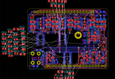
pcb.png

See why I needed a break?...

I routed the three ICs on the right and the bottom left one, plus all the ground and power bus in the middle (the three top ICs were already routed), and yes, I know the middle bus takes a lot of real estate but that's the best I can do on a 2 layers board (it really should be a 4 layers one...).

I still don't know if everything will fit (I have a small joker as I can extend the board by a few mm on the left if I need to), it looks a bit better than before though so I'm more hopeful.
 
Back
Top