diy solar

diy solar

Developing a new BMS, feedback wanted...

You mentioned programmable wet relays for things like heating pads. Will these be just relays or full ports to run heating pads?
The JK BMS has ports for heating pads. The issue is that they only switch on when low temp cut off is activated.
This is great when just storing batteries but not as useful if you want to be using them in freezing temps.
What would be nice is to be able to program them so they came on at say 38°F and kept the batteries warm enough that the low temperature cut off is never triggered.
 
With cells getting bigger you can end up with 200 lb plus batteries. These are hard enough to handle in a shed and almost impossible in a mobile platform. But four 50lb batteries in series is a lot more manageable.
So the idea that the BMSs of smaller batteries in series could communicate and work together as one battery sounds pretty cool.
 
Last edited:
You mentioned programmable wet relays for things like heating pads. Will these be just relays or full ports to run heating pads?
The JK BMS has ports for heating pads. The issue is that they only switch on when low temp cut off is activated.
This is great when just storing batteries but not as useful if you want to be using them in freezing temps.
What would be nice is to be able to program them so they came on at say 38°F and kept the batteries warm enough that the low temperature cut off is never triggered.

Not sure what you mean by full port, maybe you mean powered? They won't be powered, as it requires a much larger step down converter for us to have onboard, and probably wouldn't provide enough power anyway. Instead these will be relays, so for something like a heating pad as long as it doesn't exceed the ratings of the relay, you just pass the power through it and the relay can turn it on/off. The ones we'll use will be AC and DC rated, so you can use either type of load (but not crazy, I would figure around 3A each), and the intention is that they'll be used for heating pads, or any other kind of load you might want to toggle. As far as the logic goes - I'm not 100% sure yet what we'll be doing - it will certainly be programmable, so at worst you'd be selecting what criteria would toggle the relay on/off (such as temperature, etc), and it wouldn't be tied directly to a particular function. I'm leaning towards having them use our scripting system, then you could have more sophisticated logic control them than just something like temperature below X number. We also have PWM fan's with PID control to maintain target temperatures, so we could even look into having a relay/temperature PID control, which would be much more stable than just toggling on/off when it exceeds a particular temperature.

With cells getting bigger you can end up with 200 lb plus batteries. These are hard enough to handle in a shed and almost impossible in a mobile platform. But four 50lb batteries in series is a lot more manageable.
So the idea that the BMSs of smaller batteries in series could communicate and work together as one battery sounds pretty cool.
The key thing to keep in mind with networking them this way is that communications aren't instant, as even on a local network we're talking probably around a couple milliseconds from some signal being triggered on one device, generating the packet for the master device, and then the master receiving and decoding. So if you're talking about having let's say 4x 48v batteries in parallel it would probably work fine to turn them all off if one goes offline, etc - but I wouldn't use it to take 4x 12v batteries in series (to make 48v) and turn them into a single big battery.
 
Why not? I mean at least something simple like inter-battery balancing could be done on the order of ms, no?
I'm thinking more of the behavior when one or more packs go offline - so let's say that it's 4x batteries of equal size. In the parallel example, if one battery goes offline, the other 3 will see an increase of ~33% as the load is now spread across 3 instead of 4 cells. Even if you were running at the max amps for some reason, I think most systems can handle extra demand for a second or two so a couple ms should be more than ok. But in the series example, if one battery goes offline you're now supplying at 36v instead of 48v, and I suspect that would cause all sorts of additional issues as it's probably well below the expected voltage. People can do whatever they want ultimately, but I would avoid using it for series unless the cutoff was well under 1ms - but as I said, that's just my opinion and everyone's system is effectively unique.
 
I can tell you some issues I have with the EG4 LifePower4 (QT-YS00-16SV100A) Narada BMS so take some of these suggestions as ways to make a better one

>Only 6 balances going on at any time, maximum shunting current is ~300mA or 10-12 ohms. I like the idea of 2A shunting current and why not all more than 6? Everybody gets one and make them PWM so you can adjust the current.

>It will stay balancing on a cell while another cell are at a much higher in voltage, software needs to jump around more. I would press the reset button and the BAL would go to the highest 6 cells. I shouldn't have had to do this. those Transistors should be bouncing all over the place. There is a minimum hold time or V drop but High V has priority.

>The lower V cells take forever (days) to come up. With more active shunts with higher current the low cell get more of the source voltage & current and would be able to charge faster. The MOSFETS are on the board with I/O attached so why not use them. Unless they are multiplexed and can only use 6 at a time.

That is opinion of an old electrics guy that gets aggravated when inanimate objects do not perform as they should.

You should be able to take unbalanced cells and put a fantastic BMS on it with a good source voltage/current and get the job done in a reasonable time.
 
I'm thinking more of the behavior when one or more packs go offline - so let's say that it's 4x batteries of equal size. In the parallel example, if one battery goes offline, the other 3 will see an increase of ~33% as the load is now spread across 3 instead of 4 cells. Even if you were running at the max amps for some reason, I think most systems can handle extra demand for a second or two so a couple ms should be more than ok. But in the series example, if one battery goes offline you're now supplying at 36v instead of 48v, and I suspect that would cause all sorts of additional issues as it's probably well below the expected voltage. People can do whatever they want ultimately, but I would avoid using it for series unless the cutoff was well under 1ms - but as I said, that's just my opinion and everyone's system is effectively unique.
Surely for a series stack when one BMS cuts off it goes high-impedance (and does not provide a low impedance bypass path)?
That means the whole series stack is zero-current; effectively supplying zero volts into any load.

I don't think your 36V will happen.

What might, however, is that the whole 400V capability of that HV inverter in charge mode gets applied to the one poor BMS
in the stack of 32S 48V modules...
Duh! You're absolutely right! :)
I can tell you some issues I have with the EG4 LifePower4 (QT-YS00-16SV100A) Narada BMS so take some of these suggestions as ways to make a better one

>Only 6 balances going on at any time, maximum shunting current is ~300mA or 10-12 ohms. I like the idea of 2A shunting current and why not all more than 6? Everybody gets one and make them PWM so you can adjust the current.

>It will stay balancing on a cell while another cell are at a much higher in voltage, software needs to jump around more. I would press the reset button and the BAL would go to the highest 6 cells. I shouldn't have had to do this. those Transistors should be bouncing all over the place. There is a minimum hold time or V drop but High V has priority.

>The lower V cells take forever (days) to come up. With more active shunts with higher current the low cell get more of the source voltage & current and would be able to charge faster. The MOSFETS are on the board with I/O attached so why not use them. Unless they are multiplexed and can only use 6 at a time.

That is opinion of an old electrics guy that gets aggravated when inanimate objects do not perform as they should.

You should be able to take unbalanced cells and put a fantastic BMS on it with a good source voltage/current and get the job done in a reasonable time.
Totally agree about the balancing logic - I have a bunch of JBD BMS's and it's super annoying that it doesn't do a better job balancing (even considering it's passive). Some of the balance logic is going to be limited by what the TI chip allows (in particular the passive portion), but I'd like to have the system be far more robust. I have some ideas I'm interested in experimenting with, but it's just guesses until we finalize the hardware design.
 
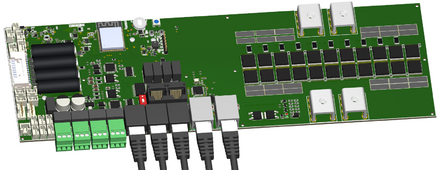
We've got the first parts layout roughed in - keep in mind this is not final parts or parts placement, it's just to get an idea of where we're putting key components, connectors, etc - so I thought a good time to get feedback again. In terms of connectors, there's a couple that will be removed, but here's the general gist:

Upper left of board: Reset button header, Action button header, RGB LED (WS2812) header, Piezo header. The board has all of these on the actual device as well, but also headers for external ones if needed.
Middle left: Cell current sense connector, 4x NTC connectors
Bottom left: 2x PWM fan connectors, 2x contactor connectors (dedicated), 3x general purpose inputs and 3x general purpose outputs
Bottom green connectors: 4x 5A AC/DC relays, controlled via configuration (no dedicated purpose)
Bottom black RJ45's: RS485, CAN, RS232.
Bottom silver RJ45's: Ethernet in/out (onboard switch)
Black face up RJ45's: Internal use for communication between BMS boards.

So if you think there's anything missing, or if you have some comments/opinions about placement, let me know. Most of the locations now are based on kind of optimal use, like for connecting the battery negative, we're spaced a bit to allow for a heat sync on the mosfets (there's additional components on the back side of the board). Some of the open regions are placeholders for other parts that don't have external connectors or hard and fast positioning requirements. We don't necessarily have a ton of flexibility on moving things around, but it if something is a big deal we can look into it.

BMS-1.png
 
Any possibility of spreading those little connectors out, some of them might be difficult to unclip when the board is well populated and some of us have fat fingers.
 
Processor-wise we're using the ESP32-S3R8N16 (it's the standard processor we use these days)

Don't do everything with one CPU. Use two, or better yet an FPGA state machine.
Do the logic with no undefined states, all unused codes go back to a recovery point. Traffic light controllers are done this way, reducing service calls. Even map it to rad-hard cells (3-way redundancy with voting logic) so cosmic particles don't upset operation.

Protection against damage should be rock solid, free from bugs. Adjustable parameters should be securely stored somewhere, in a manner that doesn't let bad code easily trash them.

Updates to monitor, communications, etc. should be possible on separate CPU without needing to do regression testing on the cell protection code.

Updates sometimes fail or brick. Have two images (or more), where if an update goes wrong it can reboot to previous working code. "Restore" points.
 

diy solar

diy solar
Back
Top