diy solar

diy solar

DIY BMS design and reflection

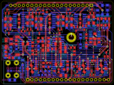
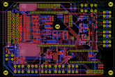
I took a pause from routing the HWPB and I've done almost all the corrections and ameliorations I wanted to make on the BMSB.

What's left is to add some resistors and jumpers on the shunt op-amp to be able to select between 50, 75 and 100 mV shunts without having to change the resistors values; and change U150 for op-amps with a better Vos as right now it's a bit high to my taste, I want more accuracy, especially for the shunt measurement.

pcb.png
 

Attachments

  • BO_BMSB_1630.pdf
    280.6 KB · Views: 7
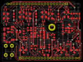
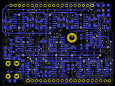
Today I've corrected the error I made on the DPB and I've improved a few things routing-wise while I was at it:

pcb.png

I'm now doing the BOM for it as I've only done it partially while doing the schematic.
 

Attachments

  • BO_DPB_1630.pdf
    224.5 KB · Views: 7
I am a power electronics engineer and this is an exciting project.

For quite some time, I was looking for a 16S BMS that satisfied all my hopes and dreams but gave up. I have the skills and tools to design and make one from scratch, but lack the time.

Would love to dive into this......
 
Thanks ;)

Time is the biggest factor here, I'm well into the hundreds of hours already...

Would love to dive into this......

Advices and remarks are welcome if you have any ;)

//

I've finished the BoM for the DPB and the cost is around 130 USD of materials including PCB, copper busbars and heatsinks (but not including the bolts, can't be bothered to search for that right now...) VAT not included. Not too bad for a low loss 300 A continuous SSR with precharge and other features using top tier components ?
 
Thanks ;)

Time is the biggest factor here, I'm well into the hundreds of hours already...


Advices and remarks are welcome if you have any ;)

//

I've finished the BoM for the DPB and the cost is around 130 USD of materials including PCB, copper busbars and heatsinks (but not including the bolts, can't be bothered to search for that right now...) VAT not included. Not too bad for a low loss 300 A continuous SSR with precharge and other features using top tier components ?


Indeed! Not bad BOM cost.

I have a commercial pick and place line and advanced manual assembly - so making a test system is not much of a hurdle.
 
Having my own PnP would be nice, especially for this project, but I can't (at least right now...) for a lot of reasons, money being the first.

Tonight I'll try to finish the HWPB routing, it should be possible if I'm a bit lucky ?
 
Those last few weeks I have been extremely busy (mainly because I started a new job) so I haven't been able to do much but I found some time to make a few layouts for the annunciators panel (NB: I'll probably center the texts in their columns on the real layout):
- vertical https://pastebin.com/6uP80QgP
- square 1 https://pastebin.com/CLcEYs5n
- square 2 https://pastebin.com/8kLiqG3w
- horizontal https://pastebin.com/VcF4TD9N

The best one to me is the horizontal one followed by the square 1.
 
That's the one you really don't want to be lit...

The hardware one is set if any of the temperature sensors (excluding the aux one) gets above 117 °C.

Same for the software one but the threshold temp is user settable; default value will probably be 110 °C.

NB: on the layouts above the different annunciators will be grouped in titled frames ("status", "master alarms", "software alarms" and "hardware alarms") so they can be identified easily.
 
Last edited:
  • Like
Reactions: Cal
Any thoughts of scaling the design down to 4S? And no FET disconnects, something similar to Chargery? I believe there will be a large demand for RV's. There will be a major transition soon.

Have you breadboarded your design? At least the critical portions? Or waiting for circuit boards for initial testing?
 
Any thoughts of scaling the design down to 4S?

Yes, I plan to do 8S and 4S models (8S will be very similar to the 16S, and 4S will be re-designed from scratch for the cells voltage measurement as I can greatly simplify it with that small number of cells) but only once I finished this one ^^

And no FET disconnects, something similar to Chargery?

That's part of why I went for a modular design. This model is already compatible with a relay based disconnect actually, you just need to add a small interface board: basically you need IC410 and its passives, and add some transistors to drive the relays. If you want the precharge/recovering features you just add D301 and its passives to generate V_PRECHG_TEST, F301 and the power resistors, and D201, that's all.

Have you breadboarded your design? At least the critical portions? Or waiting for circuit boards for initial testing?

No, I'll wait for the PCBs as 95 % of the components are SMD so not really breadboard friendly. I've done a lot of datasheets reading and calculations to avoid most of the problems I could encounter, and I've re-read the schematics a lot with new eyes each time in hope to catch all the dumb mistakes before ordering the PCBs.
 
  • Like
Reactions: Cal
Yes, I plan to do 8S and 4S models (8S will be very similar to the 16S, and 4S will be re-designed from scratch for the cells voltage measurement as I can greatly simplify it with that small number of cells) but only once I finished this one ^^

In that case I would have added my opinion on some of the design options.

I like the option of plugging in a buzzer for notification of disconnects or other issues.

There's no display? Just LEDs?

Data streaming? I like it simple like RS232.

What's your estimated fet (disconnect) ON resistance for a 300A unit? Would you be using the same (high voltage) fets for a 4S & 8S system?
 
In that case I would have added my opinion on some of the design options.

Sure, that's what this thread is for ;)

I like the option of plugging in a buzzer for notification of disconnects or other issues.

Already included on the HMI board, disablable by a jumper for those who are annoyed by beepers ?

There's no display? Just LEDs?

Main data feed is the ethernet one. The HMI has only LEDs because it's meant as a very simple and quick to read summary of the most important informations only.

You can use your phone/tablet/PC/... check the data via the ethernet or if you want a standalone unit like some other BMSs you can strap a raspberry pi on the back of any screen you like (you want a 50" screen for your BMS? you can! :ROFLMAO:).

Data streaming? I like it simple like RS232.

Yes, of course ? lots of data and also lots of parameters you can adjust if you don't like the default values. The ethernet com will be via a JSON API so you can write your own client with or without a GUI as you prefer (I'll obviously make a GUI client, ideally just a single file web app, but if for some reason you don't like it or want to make a hardcoded mobile app or whatever, well, you can). The main reason is that APIs are very versatile, low overhead (I use an arduino nano, not a PC...), and I'll have lots of other things on the same network who will be able to get/send data from/to any other node on the network to make better and more efficient decisions (like for example activating the water heater if the battery is full and there's still plenty of sun). And the main reasons for the ethernet instead of serial, BT, wifi, ... are detailed in the first pages of the thread (but mainly: reliability, distance, speed, widespread, ...).

Now, the ethernet is just a shield and talks to the arduino via a SPI port. So if you don't like it you can totally ditch it and use the SPI directly or any other protocol that can fit on 4 wires (pretty much all of them ^^); you just need to be careful as the port is shared for the ADC so you need to stop talking when the ADC is selected but that's all.

What's your estimated fet (disconnect) ON resistance for a 300A unit?

Typical will be 0.38 mOhm (for Tj = 120 °C, 0.22 mOhm @ Tj = 25 °C) and max will be 0.48 mOhm (for Tj = 120 °C, 0.28 mOhm @ Tj = 25 °C). You need to add the PCB traces resistance but it'll be very low (basically I made it as low as I could) given the busbars and short distance.

That translates to those power figures per mosfet (for Tj = 120 °C, values are slightly rounded; design is based on 300 A continuous and 400 A peak for 20 sec constraints):

typ 0.19 W @ 100 A (3.8 W total)
typ 0.76 W @ 200 A (15 W total)
typ 1.7 W @ 300 A (34 W total)
typ 3.0 W @ 400 A (61 W total)

max 0.24 W @ 100 A (4.8 W total)
max 0.96 W @ 200 A (19 W total)
max 2.2 W @ 300 A (44 W total)
max 3.8 W @ 400 A (77 W total)

Which is 99.78 % efficient (99.72 % worst case) for 300 A at 3.2 V nominal/cell.

Edit: for fun I calculated at 100 A and I get 99.93 % typical, 99.91 max.

Would you be using the same (high voltage) fets for a 4S & 8S system?

No because there's no good reason to do that and lower voltage mosfets are less expensive and have a lower Rdson, but I'll leave more margin as here the 80 V mosfets are a bit tight for a 64 V max system so the TVS don't protect the them as much as I'd want (but the mosfets are avalanche rated well over what they should see, so that's okay; I'd just wanted more margin ideally).

But if you change a few components on the 16S disconnect board (IIRC just the 4 power resistors and the PTC fuse, and maybe the resistor biasing the zener) you'll be able to use it with the 4S and 8S BMS board if you want (no changing of the connector type or pinout BS like apple likes to do...). Actually you'll be able to use it as is but the precharge/recovering currents will be far lower than what they should be (and V_PRECHG_TEST might not be in specs so you may still need to change the zener bias resistor).
 
I haven't worked with ethernet. Would an Arduino datalogger require an ethernet shield? That's not an easy interface.

Shield
 
Yes. There's libs already made so that helps. The easiest solution is to use a raspberry pi as they already have all that's needed, including lots of logging space. But as I said above you can just avoid the ethernet and use the com you prefer instead ;)

I should have some spare I/Os on the 4S version so I'll try to add a serial com for those who don't like the ethernet.
 
  • Like
Reactions: Cal
Yikes, raspberry pi consumes at least 700 mA. I'm looking for 20 - 30 mA.

Adding a serial com would be great!
 
Back
Top