Boron
New Member
Having been frustrated and appalled by the specious illiterate rubbish posted about home dc power grids and their components I am resolved to build a credible high current bench 24/48V (300/150A) sourced from an LFP bank (which I will also use for night rate energy storage).
I will have a DSO 50g/s and 6.5DVM, Picolog 16b 8 channel data logger plus hall effect ammeters to carry out stress tests, breaking high currents.
Components to examine
dc MCBs
Switches
Fuse types
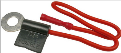
Fuse links
Wire ampacity
bolted joints
connectors
effect of speciality grease?
sustained arc flash vs gap vs voltage (with methods of extinguishing etc)
What have I forgotten?
Feel free to comment on this pursuit of knowledge by test evidence (rather than plausible conjecture BS).
Hope to add to the fount of knowledge on Solar power systems fundamentals started by our Board master @Will Prowse
You will doubtless find that most text books are centred on AC power/theory which is of course invaluable but when it comes to dc Power >15A say then you are in the wild west (as an amateur and professional Power Engineers would scoff). But who has exposure to dc traction, electroplating, telephone exchanges, large server UPS's and so on?
Yet we have discussions on 48V 300A solar panel grids and of most concern is higher voltages of ca 400Vdc
My source is the 1954 Busbar Design Manual issued by the Copper Development Association --Highly recommended to source a copy on Ebay as I did.
You would never realise the complexity of a grid of flat copper bars/fittings/switchgear/panels
I also draw inspiration from the boaty crowd ABYC. https://abycinc.org/standards/ They have many decades of experience drawn from LABs and dc systems when afloat together with a raft of official regulatory standards required by Insurers - think about it. They have a recent standard on the use of LFBs aboard. Systems must be certified by an official EE inspector of you wont get insured and may not be allowed to moor in exclusive marinas and be a danger to other craft. Electrical fires are quite common.
Heavy current in a hot marine environment - could you get a more severe test of integrity. Cowboys cant swim!
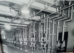
below 600Vdc 5000A busbar and switchgear room for a London underground substation
I will have a DSO 50g/s and 6.5DVM, Picolog 16b 8 channel data logger plus hall effect ammeters to carry out stress tests, breaking high currents.
Components to examine
dc MCBs
Switches
Fuse types
Fuse links
Wire ampacity
bolted joints
connectors
effect of speciality grease?
sustained arc flash vs gap vs voltage (with methods of extinguishing etc)
What have I forgotten?
Feel free to comment on this pursuit of knowledge by test evidence (rather than plausible conjecture BS).
Hope to add to the fount of knowledge on Solar power systems fundamentals started by our Board master @Will Prowse
You will doubtless find that most text books are centred on AC power/theory which is of course invaluable but when it comes to dc Power >15A say then you are in the wild west (as an amateur and professional Power Engineers would scoff). But who has exposure to dc traction, electroplating, telephone exchanges, large server UPS's and so on?
Yet we have discussions on 48V 300A solar panel grids and of most concern is higher voltages of ca 400Vdc
My source is the 1954 Busbar Design Manual issued by the Copper Development Association --Highly recommended to source a copy on Ebay as I did.
You would never realise the complexity of a grid of flat copper bars/fittings/switchgear/panels
I also draw inspiration from the boaty crowd ABYC. https://abycinc.org/standards/ They have many decades of experience drawn from LABs and dc systems when afloat together with a raft of official regulatory standards required by Insurers - think about it. They have a recent standard on the use of LFBs aboard. Systems must be certified by an official EE inspector of you wont get insured and may not be allowed to moor in exclusive marinas and be a danger to other craft. Electrical fires are quite common.
Heavy current in a hot marine environment - could you get a more severe test of integrity. Cowboys cant swim!
below 600Vdc 5000A busbar and switchgear room for a London underground substation
Attachments
Last edited: