diy solar

diy solar

Best way to transport inverter power 200 feet?

Zero_PD

New Member
Joined
May 20, 2022
Messages
38
Location
SF Bay Area
Hi there,

I have three Growatt inverters wired in parallel. Due to some constraints, I need to power something 200 feet away. I'm trying to figure out the cleanest way to do this in a safe DIY fashion.

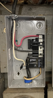
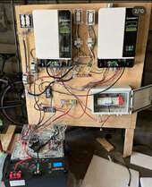
Previously I've manually wired up three bus bars that I use to connect the Line/Neutral/GND of my AC outputs. Then I've wired that to outlets with a circuit breaker on the Line. Very straight forward, very DIY. Pic below. But I'm wondering if I should step it up. Should I use an actual circuit breaker box to connect the AC outputs of my inverters? And then, how do I best move this power 200 feet? I guess I could trench 6 gauge wire and then have a second circuit breaker box on the far end, or just wire up outlets at the far end?

Would love any advice. Thanks.IMG_9355.jpg
 
Disclaimer: I'm not an electrician, but I think I'd be inclined to:
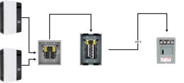
  • use a small breaker box as a combiner box to parallel the two inverters - instead of the bus bars
  • have a larger breaker box with a main breaker as your "main panel"
  • feed your nearby outlets using breakers in the "main panel"
  • use another smaller breaker box as a "sub panel" at your location 200 ft away and feed the outlets there using breakers in that panel
parallel_inverters_with_sub_panel.png
 
Last edited:
Absolutely you should be using a proper J box or small breaker panel to make connections and distribute branch circuits. The set up in the pic with exposed bus bars, free air splices and breakers is dangerous and needs to be corrected. I would be inclined not to provide any further advice regarding expanding the system until corrections are made.
 
Absolutely you should be using a proper J box or small breaker panel to make connections and distribute branch circuits. The set up in the pic with exposed bus bars, free air splices and breakers is dangerous and needs to be corrected. I would be inclined not to provide any further advice regarding expanding the system until corrections are made.
Yeah, that’s a real mess, rip out all that AC stuff and start over with proper breaker boxes. Not sure you need combiner then main but that’s just plain unsafe.
 
You don't need two load centers to combine the two inverters. You can do it in one box but the back fed breakers have to have retention per NEC. While you're at it download a copy of the NEC and READ. Your wiring as depicted is scary.
 
Absolutely you should be using a proper J box or small breaker panel to make connections and distribute branch circuits. The set up in the pic with exposed bus bars, free air splices and breakers is dangerous and needs to be corrected. I would be inclined not to provide any further advice regarding expanding the system until corrections are made.

I agree, that board is quite messy with some very questionable decisions. I think it needs to be much more organized. For example the 3 horizontal busbars have GND and Nuetral seperated by the Hot. While I agree with there being a nuetral and a ground busbar I wouldn't put the hot in between them. There's also shouldn't be a splice outside of the 2 gang box, I'm not even sure why that would be there.
 
Thanks! I'm aware my wiring in the included pictures is pretty rough and unsafe. While I did install covers over the bus bars, then taped around them, it was still quite rough compared to any real electrical work. This was for a brief (week long) offgrid application and access to this control panel was limited. Still, I am hoping to do better this year, which is why I am coming to you one folks for advice.

Let me start with step one. I do not know how to use a breaker box to wire my three Growatt inverters in parallel. I find breaker boxes weirdly confusing. Connecting to bus bars made sense in a way this hasn't yet clicked for me. Most YouTube videos describe how to wire one up for a house or how to install a circuit breaker. I was in a rush like year so using three bus bars made more intuitive sense and I ran with it. In the one pictured below, how do I most successfully wire three Growatts in parallel using it?

Any advice is appreciated. Thanks for your patience.

1721321734696.png
 
Disclaimer: I'm not an electrician, but I think I'd be inclined to:
  • use a small breaker box as a combiner box to parallel the two inverters - instead of the bus bars
  • have a larger breaker box with a main breaker as your "main panel"
  • feed your nearby outlets using breakers in the "main panel"
  • use another smaller breaker box as a "sub panel" at your location 200 ft away and feed the outlets there using breakers in that panel
View attachment 229499

Similar to where I was going to go. If you watch many of Will's videos, (and IIRC) he commonly uses an e-panel with solar feeds going *in* to individual breakers, and then uses the resulting common bus feeds to other breakers *in the same panel* to go *out* to loads. He essentially combines the two e-panels on the left of your diagram into a single e-panel.
 
Thanks! I'm aware my wiring in the included pictures is pretty rough and unsafe. While I did install covers over the bus bars, then taped around them, it was still quite rough compared to any real electrical work. This was for a brief (week long) offgrid application and access to this control panel was limited. Still, I am hoping to do better this year, which is why I am coming to you one folks for advice.

Let me start with step one. I do not know how to use a breaker box to wire my three Growatt inverters in parallel. I find breaker boxes weirdly confusing. Connecting to bus bars made sense in a way this hasn't yet clicked for me. Most YouTube videos describe how to wire one up for a house or how to install a circuit breaker. I was in a rush like year so using three bus bars made more intuitive sense and I ran with it. In the one pictured below, how do I most successfully wire three Growatts in parallel using it?

Any advice is appreciated. Thanks for your patience.

View attachment 229533

I'm going to assume that each Growatt feeds one phase (L1 or L2) in a split-phase configuration. Just make sure that when you install the correct breakers as *inputs* to the panel from each of the Growatts, that the two breakers are directly next to each other, with one *above* the other. This will help insure that each Growatt inverter is supplying one of the two phases (L1 or L2) in the panel. There are other ways to do this, but above and below is easier to keep track of (to me, at least).

Also, assuming this is a totally off-grid system, you'll need to run a #6AWG copper wire to a Grounding rod at the "main" panel, and bond Neutral to Ground in the main panel. The N-G bonds in the inverters need to be disabled. The only N-G bond and Grounding rod should be at the main. The Grounds for everything should be tied down there, including conduits and panel frames.

My advice comes with caveats: I'm not an electrician. I'm an EE. Different skill set, but I've picked up some electrician knowledge along the way. Some might say, just enough to be dangerous.

Doing any of this is absolutely at your own risk (as with anything else you do from learning at this site).

Please remove everything in your OP photo, and start over. What you've got is downright dangerous.

ME here. Mechatronic really. Just enough electrical skills to be dangerous too. Obviously haha by my past wiring. Yes, I plan to uninstall these bus bars and do much better.

I'm still trying to understand how to use a breaker box to parallelize my three Growatts. I am adding a third one in to the picture I shared. It sounds like you connect the Neutral and Hot lines to breakers and plug them into the breaker box. And then you use the shared bus bars as OUT to...another breaker box, where your loads go? I think that is what @Symbioquine was sharing in his diagram.

@Recovering EE - why do I need to disable the N-G bond within the Growatts? Last year, in the picture, 3 separate bus bars that paralleled Line, Neutral, and Ground. N and G were tied together within the Growatts and then of course was shared via the bus bars. I fortunately had no issues.

The Neutrals should connect to the common Neutral busbar in the e-panel, and the Grounds should connect to the common Ground busbar in the e-panel. The e-panel common Ground busbar connects to the Ground rod. Neutral and Ground busbars should be connected in the e-panel (the N-G bond). Often (depending on the e-panel) there's simply a screw hole that goes all the way through the Neutral busbar that you can put an N-G bonding screw in and tighten all the way down to the e-panel case, that effectively connects the Neutral busbar to the Ground busbar. The Ground busbar default should already be connected to the case, with the Neutral busbar *probably* floating. Or you can just connect them together with a piece of copper wire. I use #6. Note: Some e-panels come with the N-G bonding screw already installed.

Connecting Neutral to Ground in multiple places can lead to Ground loops, which can set up oscillations that can wreak havoc on electronics. Doing so is best avoided, and probably violates code, to boot. That it hasn't caused problems in your case is probably luck. Without changing anything else at the same time (and after installing a ground rod at the main), I'd try things out with *only* the N-G bond at the main e-panel, but make darn sure that every exposed metal bit (cases, conduit, panel frames, etc) and inverters are all Grounded at the main e-panel Ground.
 
Thanks! So..

I parallelize the three Growatts by connecting their Ground and Neutral lines to a bus bar within a breaker box and then connecting their Hot/Line connections to a circuit breaker which slots into the rail. Does that smaller breaker still need a Main Breaker to turn the whole box on and off or should I just it as a passthrough?

Then I utilize the shared bus bars to go out to a SECOND breaker box which my loads are actually tied to, and this acts as a "standard" breaker box.

Does this sound about right?
 
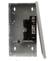
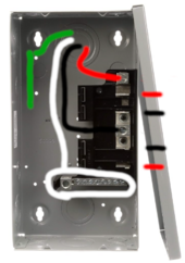
If I used this circuit breaker below to parallelize my three Growatts, I could just acquire 3x 30A QP breakers to slot in, and then could I connect both Neutral and GND from my Growatt to the same neutral bus bar? I believe 30A would be accurate as I don't want to throttle the 25A max output from the Growatt SPF 3000TL LVM-ES.

I am unsure whether you need a separate GND and Neutral bus bar.
In this YouTube video here he connects GND and Neutral to the same busbar. However, some commenters say they bought and installed their own GND bar. Which would yall recommend?

(
)

Screenshot 2024-07-18 at 5.50.52 PM.png
 
Last edited:
Just run some romex to another panel, or… extension cords.. I guess it depends on what you wanna run.
 
I’m all in favor of DIY, but when it comes to electricity, only where you either 1) know what you’re doing, or 2) have a friend/electrician who does know to help you. PLEASE stop what you’re doing until one of those two things happens. This stuff can kill you or burn your house down.

That said, I see multiple problems (in addition to what others have pointed out).

First, is that wood structure anchored anywhere? It looks like the legs are made from 1X6. If you’re going to use it, it should be sturdy, and anchored. There’s this guy named Murphy, and he’s back there smiling and waiting to tip that whole thing over.

Second, that PV combiner box appears to be ungrounded. Not good. Does the PV come in from the back side? Keep in mind that PV can be hundreds of volts, of DC current. (See note above about how this stuff can kill you). All of that PV cable should be in metal conduit. And that exposed Wago (?) connector is a no-no even for basic 120-volt AC, much more so for 400-volt DC.

Are you intending for your setup to be just 120 volt? Or 120/240? Pretty much all consumer/household breaker panels are two-bus 120/240. Which you can use for single-phase 120, but it’s not recommended and there are lots of things you’ll need to do. Tell us whether you want 120 or 120/240 and maybe we can go from there.

Like others have said, the bus bar approach to your AC wiring is a bad idea. Much better to wire into backfeed breakers going into a panel. Or at the very least, use finger-safe PDBs or Polaris connectors. Also, get used to the idea that ALL connections should be enclosed, not in free air.

Finally, not so much a safety issue, you have bus bars for your battery connections, but aren’t using them to combine your batteries. Why? Instead of stringing battery cables from one battery to the next, make a cable from each battery directly to the bus bar, and then from the bus bar to inverters. Fuse appropriately. Which means that you fuse for the wire on each segment.

Good luck. Be safe.
 
an e-panel with solar feeds going *in* to individual breakers, and then uses the resulting common bus feeds to other breakers *in the same panel* to go *out* to loads. He essentially combines the two e-panels on the left of your diagram into a single e-panel.

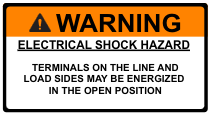
I know you can do this, but I think it's cleaner and easier to understand if you have one panel that has the sole purpose of combining the inverter outputs. Which can have some big warning stickers on it.

1721397293679.png
1721397315039.png
(I think it maybe should have one saying "Do not add loads" for good measure, but I can't find that one right now...)

By the same token, I think it's also safer because it means you can turn off the main breaker in your "main panel" when doing work like adding circuits instead of needing to turn off a combination of backfed breakers. (Even if they're all tied together, it still takes more thought in the moment.) This makes it nearly like the panels in the majority of homes in America - there is a safety factor to having things be as standard and unsurprising as possible.

Does that smaller breaker still need a Main Breaker to turn the whole box on and off or should I just it as a passthrough?

No, the inverter combiner panel doesn't need to be a main breaker panel. If you need to do work in there, you turn off the inverters (and verify they're not supplying voltage first). If you need to do work downstream of that, you can turn off the main breaker in your "main panel".

Are you intending for your setup to be just 120 volt? Or 120/240? Pretty much all consumer/household breaker panels are two-bus 120/240. Which you can use for single-phase 120, but it’s not recommended and there are lots of things you’ll need to do. Tell us whether you want 120 or 120/240 and maybe we can go from there.

It seems pretty clear since there's two inverters right now and OP is trying to add a third, that they're all in parallel on a single leg at 120v. Also evidenced by the hot lines of both existing inverters are tied together on the bus bar currently.

OP should maybe consider a split phase system at some point, but AFAIK most inverters that support that require an even number of inverters on each leg so it probably wouldn't work with the 3 inverters that OP wants to hook up.
 
No, the inverter combiner panel doesn't need to be a main breaker panel. If you need to do work in there, you turn off the inverters (and verify they're not supplying voltage first). If you need to do work downstream of that, you can turn off the main breaker in your "main panel".

Thanks! Still learning about circuit breaker panels. Is it okay to use the one neutral bus bar in the box I pictured to connect both ground and neutral from each of my inverters? For some reason I found breaker boxes very hard to read - I can't "see" how they work, which is why I previously just used three bus bars to parallelize my inverters and then took that out to fuses and outlets. At least I understood what was going on. In the above pictured breaker box, I still can't look at it and see where my GND/Neutral/Line would go out to the second breaker box.

Second, that PV combiner box appears to be ungrounded. Not good. Does the PV come in from the back side? Keep in mind that PV can be hundreds of volts, of DC current. (See note above about how this stuff can kill you). All of that PV cable should be in metal conduit. And that exposed Wago (?) connector is a no-no even for basic 120-volt AC, much more so for 400-volt DC.

Are you intending for your setup to be just 120 volt? Or 120/240? Pretty much all consumer/household breaker panels are two-bus 120/240. Which you can use for single-phase 120, but it’s not recommended and there are lots of things you’ll need to do. Tell us whether you want 120 or 120/240 and maybe we can go from there.
Hi there. I want a pretty simply 120V setup. 3 Growatts in parallel for a 9k output. Should I not use circuit breaker boxes to parallelize my 3 growatts after all?

For the combiner box, two strings of solar panels come in and then the output is wired directly to a Growatt inverter. So the PV panels and inverter share a ground and of course the inverter is also tied to the battery gnd. Where should I add an additional ground to my combiner box? This year we are planning to add a grounding rod to our setup.
 
Again, not an electrician - not official "advice" - but here goes...

Is it okay to use the one neutral bus bar in the box I pictured to connect both ground and neutral from each of my inverters?

In some scenarios this might be technically okay, but don't do it. Instead, I think it's simpler and clearer to just always use a ground bar - adding one to each panel if not pre-installed.

For some reason I found breaker boxes very hard to read - I can't "see" how they work

Not to be mean, but - like others have indicated - this is part of the core stuff you should make sure you understand before working on household AC power systems/wiring.

I can't "see" how they work, which is why I previously just used three bus bars to parallelize my inverters

The good news is that breaker boxes are basically a prepacked set of bus bars with standardized places to put breakers hanging off them.

In the above pictured breaker box, I still can't look at it and see where my GND/Neutral/Line would go out to the second breaker box.

It is intended to be wired like this;
1721480767213.png1721481391149.png
  • Green: Ground
  • White: Neutral
  • Black: L1
  • Red: L2 (You won't have this wire coming out of your box)
This panel doesn't have enough spaces in its intended configuration for 3 separate breakers on L1 so it wouldn't be my first choice for paralleling your 3 inverters. That said, it might be possible since you could put two of them on a "tandem" 30A single pole circuit breaker (assuming you can find one that goes with this panel).

I'm not sure if it would be code compliant, but another strategy might be to tie L1 and L2 together inside the panel. (This gets tricky since I don't think you're allowed to double up the wire in those lugs and the wire will probably be a bit large for standard wire nuts.) Then you could use 3 single 30A breakers.

Either way, with your hypothetical breaker box. Conduit connects each of the inverters to the "inverter combiner" breaker box. In those conduits;
  • Ground from each inverter comes into the breaker box and connects to the ground bar.
  • Neutral from each inverter comes into the breaker box and connects to the neutral bar.
  • Hot/Line from each inverter comes into the breaker box connects to the breaker terminal for that inverter.
Coming out of that "inverter combiner" breaker box. Conduit connects to your "main panel" breaker box. Inside that conduit;
  • Ground goes from the aforementioned ground bar to the ground bar in the main panel.
  • Neutral goes from the big lug of the aforementioned neutral bar to the big lug on the neutral bar in the main panel.
  • Hot/Line goes from the big L1 lug of the inverter combiner breaker box to the big L1 lug in the main panel. (The later lug should have a cover and feeds through the main breaker for your main panel.)
Next we consider how grounding/bonding works;
  • Run a big 8 awg copper wire (bare or green insulation) from the ground bar in your main panel to all your grounding rods (probably more than one at some distance from each other). This is the one place that such a connection to the earth will exist anywhere in your system.
  • Make sure the "inverter combiner" breaker box does not have any connection between the neutral and ground bars (check with multimeter before installing).
  • Refer to the inverter manufacturer's recommendations for how to handle bonding with parallel inverters - and any AC inputs (if any) you plan to feed into them.
    • E.g. If you were going to feed inputs that have their own neutral-ground bond, then you can't do the neutral-ground bonding in your main panel and instead need to rely on the neutral-ground bonding relay in your inverter(s). (But it isn't clear if the paralleled inverters coordinate between themselves to only enable only one such relay so you would need to confirm that.)
    • The simplest thing is to not use any AC inputs to your inverters (or at least any that have their own neutral-ground bonding), disable the neutral-ground bonding in the inverters, and make sure the neutral-ground bonding screw is in place in your main panel.
  • Make sure your sub panel(s) (the 200 ft away one when you get there) does not have any connection between the neutral and ground bars (check with multimeter before installing)
On the solar side of things;
  • Your solar combiner box should have a ground bar which is connected to the ground bar in your main panel.
  • The panel frames should be connected to the ground bar in your solar combiner box.
  • The +/- wires from your strings of solar panels go (in conduit) to the solar inputs on the hybrid inverters.
 
Thank you again. This is very helpful. You are correct that I have to figure out circuit breaker boxes haha. It is time! With that in mind just a few more questions.

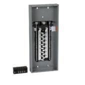
The circuit breaker box I pictured said it had “four space” so I thought this meant that four circuit breakers could be plugged in, which was one more than I needed for my 3 Growatts. I must be misinterpreting. So I’ll look for a bigger one.

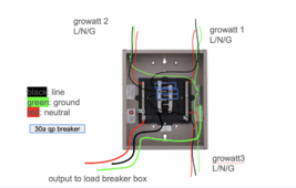
I found what looks like a standard box here. Based on all you've said I have made a diagram of what I’m thinking. Does this look correct? In the picture below, I can't figure out where a "main" breaker would go that turns off the whole box.

Screenshot 2024-07-20 at 9.54.14 AM.png


Make sure the "inverter combiner" breaker box does not have any connection between the neutral and ground bars (check with multimeter before installing).
Why is this? Is this because Neutral and Ground are tied together within the growatts?
 
Thank you again. This is very helpful. You are correct that I have to figure out circuit breaker boxes haha. It is time! With that in mind just a few more questions.

The circuit breaker box I pictured said it had “four space” so I thought this meant that four circuit breakers could be plugged in, which was one more than I needed for my 3 Growatts. I must be misinterpreting. So I’ll look for a bigger one.

I found what looks like a standard box here. Based on all you've said I have made a diagram of what I’m thinking. Does this look correct? In the picture below, I can't figure out where a "main" breaker would go that turns off the whole box.

View attachment 229955
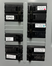
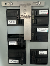
You can either buy a box that takes the main breaker at the top, or you can use a smaller box and have one of the breakers be the main feed. Here's my 'Grid' breaker panel:

Screenshot 2024-07-20 at 10.39.17 PM.png
the grid input is on the upper left, and the other breakers (including the Grid inputs to the two inverters) are loads in this box.

Here's my "House" box:
Screenshot 2024-07-20 at 10.42.07 PM.png
Where the input can be either the Grid OR the Outputs of the two inverters, and the loads are the rest of the breakers.


Note that these are 'big' one-inch breakers, you can also get 1/2 and 1/4 size that'll fit into some of the spaces of some boxes, but my electrician prefers the big ones for ease of install and reliability.
 
Why is this? Is this because Neutral and Ground are tied together within the growatts?
Neutral and Ground should be tied together in ONE place, and only one place. Most equipment has the capability of being that one place, so breaker boxes will have N-G bonding bars, your inverters have N-G connections, your meter box has a N-G bond, etc. Just pick ONE and disable or disconnect all the others.
 
Neutral and Ground should be tied together in ONE place, and only one place. Most equipment has the capability of being that one place, so breaker boxes will have N-G bonding bars, your inverters have N-G connections, your meter box has a N-G bond, etc. Just pick ONE and disable or disconnect all the others.
Thank you so much. I will look into disabling within my Growatts and then tying them together in one place within my breaker boxes.

Did the image I made look roughly correct in terms of connecting the growatts in parallel via a breaker box?
 
Thank you so much. I will look into disabling within my Growatts and then tying them together in one place within my breaker boxes.

Did the image I made look roughly correct in terms of connecting the growatts in parallel via a breaker box?
The image is hard to read, and red for neutral is a color code that hurts my brain, but it looks like you've got it. You'll want to bond both of those lugs in the middle together, I can't tell if they already are in that picture. Make sure you use wires rated for the proper ampacity.
 

diy solar

diy solar
Back
Top