diy solar

diy solar

Question about Overkill Solar (4s120a) BMS unit and B- and C- (3) wire configuration.

NCblueridge

New Member
Joined
Jul 31, 2020
Messages
154
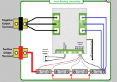
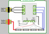
I'm finishing up my battery pack build and purchased an Overkill Solar 4s12a BMS (with the bluetooth feature). It looks to be well built.

Is there a reason there are (3) wires for the blue (B-) and black (C-) instead of typically (2) that I see on some other BMS's? I assume all (3) are needed.

Also, who did the diagram with the leads going to the busbars? Do I need to break out my soldering iron :)
 

Attachments

  • Screen Shot 2020-08-24 at 9.50.14 PM.png
    Screen Shot 2020-08-24 at 9.50.14 PM.png
    131.4 KB · Views: 59
Last edited:
Three wires are used to equal one heavier single wire to carry more current.
Those aren’t buss bars, they are your cell terminals.
You must buy small crimp on ring terminals (24g) to connect balance leads to the correct terminals.
✌️
 
Those aren’t buss bars, they are your cell terminals.
You must buy small crimp on ring terminals (24g) to connect balance leads to the correct terminals.

In the picture it sure looks like a bus bar to me. I've wondered about that as connecting a balancing lead on a terminal that has a bus bar on it seems like it could affect either battery. My guess is that the BMS will send a + or - charge that makes it affect the right battery.

Nonetheless, doesn't putting the balance lead under the head of the terminal bolt/nut versus drilling a hole for it in the bus bar serve the same purpose? If the net result is the same, it seems like a nice way to attach the balance lead. A ring terminal that correctly fits the balance wire can be used instead of something that has the right ring size but has too large of a crimp area.
 
Three wires are used to equal one heavier single wire to carry more current.
Those aren’t buss bars, they are your cell terminals.
You must buy small crimp on ring terminals (24g) to connect balance leads to the correct terminals.
Yep, that diagram was strange, I figured it out though :). I had some decent shrink wrap small ring terminals that fit those small wires. I think the main leads are 10 AWG and I had those also. All set now to do the final hookup on the BMS tomorrow, just waiting on a few more components for my build.
 
In the picture it sure looks like a bus bar to me. I've wondered about that as connecting a balancing lead on a terminal that has a bus bar on it seems like it could affect either battery. My guess is that the BMS will send a + or - charge that makes it affect the right battery.

Nonetheless, doesn't putting the balance lead under the head of the terminal bolt/nut versus drilling a hole for it in the bus bar serve the same purpose? If the net result is the same, it seems like a nice way to attach the balance lead. A ring terminal that correctly fits the balance wire can be used instead of something that has the right ring size but has too large of a crimp area.
Yep, I went with ring terminals.
 
Hummmm those alleged buss bars in said diagram are labeled
?LiFePo 4 cell?.......?
Nothing strange there. Pretty clear.
 
Last edited:
Unless referring to the part marked "negative output terminal" That could use a buss bar to link the 3 negative wire.
 
Hummmm those alleged buss bars in said diagram are labeled
?LiFePo 4 cell?.......?
Nothing strange there. Pretty clear.

I added some arrows to that image to clarify what I was talking about. No biggie though:
 

Attachments

  • Screen Shot 2020-08-24 at 9.50.14 PM.png
    Screen Shot 2020-08-24 at 9.50.14 PM.png
    133 KB · Views: 54
I told ya! :) On the serious side, I would like an explanation of if it's OK to put the lead on the bus bar instead of the terminal. Or, if it doesn't matter one way or the other. Hopefully, @OverkillSolar will provide some wisdom on this.
Yes its ok, the potential is basically the same anywhere between the adjacent terminals.
For sanity I suggest consistency though.
 
It could be the absorption of all this alcohol hand sanitizer I have been using.
 
Back to questions on the BMS. I have it hooked up to a couple of Nissan Leaf modules and reset the parameters. Trying to put a load on it and no output. In the basic information section I notice that Discharge switch says off. I don't see where that is. I tried pulling the jumper but that did not not do anything. The charging switch says on.
 
Last edited:
I asked overkill about this very picture to bus question a couple months ago via text. He said it was just easier to draw.
I have mine on the positive terminal at each connection. Working great.
 
One other thing with my OK BMS, it has a place for a temp connector but didn't come with one. Is this something I can order somewhere?

Thanks,
William
 
Back
Top